Definitions [30]
Define the unit of current.
The unit of electric current is ampere (A). When one coulomb charge flows through an electric circuit in one second, then the electric current flowing through the circuit is said to be an ampere.
Define the following:
Super conductors
Substances whose resistance decreases tremendously with decreasing temperature and reaches nearly zero near absolute zero are called superconductors; e.g., lead, tin, etc.
Define the term resistivity.
The resistivity of a material is the resistance of a wire of that material of unit length and unit area of cross-section.
A continuous and closed path of an electric current is called an electric circuit.
Current is defined as the rate of flow of charge.
Define the following:
Semiconductors
Semiconductors: Substances whose resistance decreases with the increase in temperature are named as semiconductors. E.g. manganin, constantan etc.
Define an electric current.
An electric current is measured by the amount of electric charge moving per unit time at any point in the circuit.
The magnitude of an electric current is the number of electric charges flowing through a conductor in one second.
Define the following:
Electromotive force
Electromotive force: When no current is drawn from a cell, when the cell is in open circuit, the potential difference between the terminals of the cell is called its electromotive force (or e.m.f.).
Define the following:
Conventional current
The movement of the positive charge is called conventional current.
A conductor is a material in which some charges are free to move from one part of the material to another.
At constant temperature and other physical conditions, the current flowing through a conductor is directly proportional to the potential difference across its ends.
One ohm is the resistance of a component when the potential difference of one volt applied across the component drives a current of one ampere through it.
Define temperature coefficient of resistance.
The temperature coefficient is defined as the ratio of the increase in resistivity per degree rise in temperature to its resistivity at T0.
Define Current density.
Current density is a vector quantity, often known as an area vector or cross-sectional area vector, whose value is equal to the electric current flowing per unit area.
J = `"I"/"A"`
S.I unit is A/m2.
Define the following:
Coulomb
One coulomb is the amount of electric charge transferred by a current of one ampere in one second.
The average velocity acquired by free electrons in a conductor under the influence of an electric field is called the drift velocity.
The average time interval between two successive collisions of a free electron with the ions of the metallic lattice is called the relaxation time and is denoted by τ.
Current density is the current flowing per unit cross-sectional area of the conductor. The source material connects current density with the drift motion of electrons.
Conductivity, denoted by σσ, measures how easily current flows through a material. From the microscopic model, conductivity depends on free electron density and relaxation time.
Mobility is the magnitude of drift velocity per unit electric field.
A device that does not obey Ohm's law and shows a non-linear or direction-dependent V-I relation.
A device that obeys Ohm's law and gives a straight-line V-I graph through the origin.
Resistivity, denoted by ρ, is the intrinsic property of a material that determines how much it resists current flow.
The temperature coefficient of resistivity, denoted by α, measures the fractional change in resistivity per degree change in temperature in the linear range.
- Unit: per degree Celsius or per kelvin.
- For metals, α > 0.
- For semiconductors, α < 0.
The emf of a cell is defined as the work done in carrying a unit positive charge through the complete circuit, including the charge flow inside the cell.
Unit: J/C (or) volt
The resistance offered by the electrolyte of the cell when an electric current flows through it is known as internal resistance.
When current is drawn through a cell or current is supplied to it, then the potential difference across its terminals is called the terminal potential difference.
\[V=E-Ir\]
An instrument used to measure the potential difference between two points in an electrical circuit, always connected in parallel with the component across which the voltage drop is to be measured, is called a voltmeter.
The condition of the Wheatstone bridge under which the galvanometer shows zero (null) deflection, i.e., Ig = 0, is called the balance condition of the bridge.
An arrangement of four resistors used to measure the resistance of one of them in terms of the other three, invented by Samuel Hunter Christie in 1833 and made famous by Sir Charles Wheatstone, is called a Wheatstone bridge.
Formulae [7]
I = \[\frac {Q}{t}\]
Where:
- I = electric current
- Q = charge flowing through the conductor
- t = time taken
SI unit of current = ampere (A).
V ∝ I
V = IR
Other useful forms: I = \[\frac {V}{R}\] or R = \[\frac {V}{I}\]
Using the average time between collisions ττ, the source derives the drift velocity as:
μ = \[\frac {∣v_d∣}{E}\]
where:
- vd: drift velocity
- E: electric field
ρT = ρ0[1 + α(T − T0)]
Here:
- ρT = resistivity at temperature T.
- ρ0 = resistivity at reference temperature T0.
- α = temperature coefficient of resistivity.
RT = R0(1 + αΔT)
where ΔT = T − T0.
Balance condition (when Ig = 0):
- AC → battery arm
- BD → galvanometer arm
- R4 → unknown resistance measured in terms of the other three.
Theorems and Laws [7]
According to Ohm’s law, the current flowing in a conductor is directly proportional to the potential difference across its ends, provided the physical conditions and temperature of the conductor remain constant.
No, it is not always true. E.g., Diode valve, junction diode, etc., do not obey Ohm’s law.
Statement: Ohm’s Law
"The electric current flowing through a conductor is directly proportional to the potential difference across its ends, provided the temperature and other physical conditions of the conductor remain constant."
Mathematically,
I ∝ V or V = I R
where:
- V = Potential difference (in volts)
- I = Current (in amperes)
- R = Resistance of the conductor (in ohms, Ω)
Explanation:
When two conductors at different electric potentials are joined by a metallic wire, electrons flow from the conductor at a lower potential (excess electrons) to the one at a higher potential (deficit of electrons). This movement of electrons results in an electric current.
- The current continues to flow until both conductors reach the same potential.
- For continuous current flow, a constant potential difference must be maintained across the ends of the conductor (e.g., using a battery or power supply).
Derivation / Mathematical Proof:
From Ohm’s Law:
I ∝ V ⇒ \[\frac {V}{I}\] = constant
This constant is defined as the resistance (R) of the conductor. Therefore,
V = I R ---(1)
This is the mathematical form of Ohm’s Law.
Special Case:
If the current I = 1 A, then:
V = R
This implies that the resistance of a conductor is numerically equal to the potential difference across it when 1 ampere of current flows through it.
Conclusion:
Ohm's Law provides a fundamental relationship between voltage, current, and resistance in an electric circuit. It is widely used in the design and analysis of electrical and electronic systems.
Statement
At any junction in an electric circuit, the sum of currents entering the junction is equal to the sum of currents leaving the junction.
Derivation
When the current in a circuit is steady, charge does not accumulate at any junction. Therefore, the amount of charge entering the junction per second must be equal to the amount of charge leaving the junction per second.
If currents I1 and I2 enter a junction and currents I3 and I4 leave it, then
or
Hence,
Conclusion
Kirchhoff's First Law is a direct consequence of the conservation of charge.
Statement
In any closed loop of an electric circuit, the algebraic sum of all changes in potential is zero.
Derivation
Consider a charge moving around a closed loop. After completing one full loop, the charge returns to its starting point. Since electric potential depends only on position, the net change in potential over a complete loop must be zero.
Therefore, in a closed loop,
If a loop contains cells and resistors, then the total emf supplied by the sources is equal to the total potential drop across the resistors. Thus,
Conclusion
Kirchhoff's Second Law is a direct consequence of the conservation of energy.
The algebraic sum of potential differences in a closed loop is zero.
Based on conservation of energy.
At any junction, the sum of currents entering = the sum of currents leaving.
Example: I1 + I3 = I2 + I4. Based on conservation of charge.
Obtain the balancing condition for the Wheatstone bridge arrangements as shown in Figure 4 below:
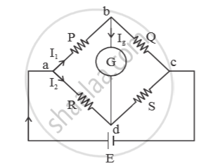
Let `I_3` and `I_4` be the currents in resistors Q and S respectively . Let `I_g` be the current through galvanometer. For balanced condition,
`I_g = 0`
Applying junction law at ‘b’ we get
`I_1 = I_3 + I_g`
`because I_g = 0 , I_1 = I_3` ....(i)
Applying junction law at ‘d’, we get
`I_2 + I_g = I_4`
`because I_g = 0 , I_2 = I_4` ....(ii)
Applying loop law in the loop abda, we get
`-I_1·P - I_g·Q + -I_2·R = 0`
⇒ `-I_1P + I_2R = 0` (`because I_g = 0`)
⇒ `I_1P = I_2R`
⇒ `P/R = I_2/I_1` ....(iii)
Applying loop law in the loop bcdb, we get
`-I_3·Q + I_4·S + I_g·6 = 0`
⇒ `-I_3·Q + I_4·S + 0 = 0 (because I_g =0)`
⇒ `-I_3Q = I_4S`
⇒ `Q/S = I_4/I_3`
⇒ `Q/S = I_2/I_1` ...(iv) [using eq.(i) and (ii)]
From eq. (iii) and (iv), `P/ R = Q/s`
⇒ `P/Q = R/S`
This is the balanced condition.
Key Points
- Electricity is a convenient and controllable form of energy widely used in homes, industries, schools, and hospitals.
- Electric current is produced when electric charges flow through a conductor, and it flows only through a closed, continuous electric circuit.
- A switch completes or breaks the circuit; when the circuit is broken, current stops flowing, and devices like bulbs do not glow.
- Electric current is the rate of flow of charge, given by the relation I = Q / t, where Q is charge and t is time.
- In metallic wires, electrons are the charge carriers, but by convention, current flows from the positive to the negative terminal, in the opposite direction to electron flow.
Resistivity and Temperature:
\[\rho_T=\rho_0[1+\alpha(T-T_0)]\]
Resistance and Temperature:
\[R_T=R_0(1+\alpha\Delta T)\]
Temperature Coefficient (α):
- Unit: °C⁻¹ (or K⁻¹)
- Metals: α > 0→ resistivity increases with temperature
Semiconductors & insulators:
α < 0 → resistivity decreases with temperature
-
In series: εeq adds, req adds.
-
If one cell is reversed in series, the net emf is the difference of emfs, but internal resistances still add.
-
In parallel, effective internal resistance decreases.
-
For two cells in parallel:
εeq = \[\frac{\varepsilon_1r_2+\varepsilon_2r_1}{r_1+r_2}\], req = \[\frac{r_1r_2}{r_1+r_2}\].
- Kirchhoff's laws are used for complex circuits.
- Kirchhoff's First Law: Total current entering a junction = total current leaving a junction.
- Kirchhoff's Second Law: Total potential rise in a closed loop = total potential drop in the loop.
- KCL is based on conservation of charge.
- KVL is based on conservation of energy.
- Mathematical forms are ∑I = 0 and ∑V = 0.
- The correct sign convention is essential in numericals.
Important Questions [77]
- Identify the Region of Negative Resistance
- In the Circuit Shown in the Figure, Find the Total Resistance of the Circuit and the Current in the Arm Ad.
- A low voltage supply from which one needs high currents must have very low internal resistance. Why?
- A Metal Sphere is Kept on an Insulting Stands. a Negatively Charged Rod is Brought Near It, Then the Sphere is Earthed as Shown.
- Two Metallic Spheres a and B Kept on Insulating Stands Are in Contact with Each Other. a Positively Charged Rod P is Brought Near the Sphere a as Shown in the Figure.
- Define Current density.
- A current of 0.8 A flows in a conductor of 40 Ω for 1 minute. The heat produced in the conductor will be ______.
- Write Its (‘Mobility’ of Charge Carriers) S.I. Unit
- Derive an Expression for Drift Velocity of Free Electrons in a Conductor in Terms of Relaxation Time.
- Define the Term Drift Velocity.
- Explain the Term ‘Drift Velocity’ of Electrons in Conductor. Hence Obtain the Expression for the Current Through a Conductor in Terms of ‘Drift Velocity’.
- Estimate the Average Drift Speed of Conduction Electrons in a Copper Wire
- When Electrons Drift in a Metal from Lower to Higher Potential, Does It Mean that All the Free Electrons of the Metal Are Moving in the Same Direction?
- Estimate the Average Drift Speed of Conduction Electrons in a Copper Wire
- Define Relaxation Time of the Free Electrons Drifting in a Conductor. How is It Related to the Drift Velocity of Free Electrons? Use this Relation to Deduce the Expression for the Electri
- A Conductor of Length ‘L’ is Connected to a Dc Source of Potential ‘V’. If the Length of the Conductor is Tripled by Gradually Stretching It, Keeping ‘V’ Constant, How Will
- A potential difference (V) is applied across a conductor of length 'L' and cross-sectional area 'A'. How will the drift velocity of electrons and the current density be affected if another identical
- Explain how free electrons in a metal at constant temperature attain an average velocity under the action of an electric field. Hence, obtain an expression for it.
- The potential difference applied across a given conductor is doubled. How will this affect (i) the mobility of electrons and (ii) the current density in the conductor? Justify your answers.
- Derive an expression for resistivity of a conductor in terms of the number density of charge carriers in the conductor and relaxation time.
- What is Its Relation with Relaxation Time?
- Estimate the Average Drift Speed of Conduction Electrons in a Copper Wire
- Define relaxation time.
- Obtain the Expression for the Current Flowing Through a Conductor Having Number Density of the Electron N, Area of Cross-section a in Terms of the Drift Velocity Vd .
- Two conductors, made of the same material have equal lengths but different cross-sectional areas A1 and A2 (A1 > A2). They are connected in parallel across a cell. Show
- How Does Drift Velocity of Electrons in a Metallic Conductor Vary with Increase in Temperature? Explain.
- A wire whose cross-sectional area is increasing linearly from its one end to the other, is connected across a battery of V volts. Which of the following quantities remain constant in the wire?
- Consider two conducting wires A and B of the same diameter but made of different materials joined in series across a battery. The number density of electrons in A is 1.5 times that in B.
- On the basis of electron drift, derive an expression for resistivity of a conductor in terms of number density of free electrons and relaxation time. On what factors does resistivity
- Why Alloys like Constantan and Manganin Are Used for Making Standard Resistors?
- Derive an expression for drift velocity of electrons in a conductor. Hence deduce Ohm's law.
- Plot a Graph Showing the Variation of Stopping Potential with the Frequency of Incident Radiation for Two Different Photosensitive Materials Having Work Functions W1 And W2 (W1 > W2).
- How Does the Resistivity of a Semiconductor Change with Rise of Temperature ? Explain.
- A Heating Element is Marked 210 V, 630 W. What is the Value of the Current Drawn by the Element When Connected to a 210 V Dc Source?
- Two Wires of Equal Length, One of Copper and the Other of Manganin Have the Same Resistance. Which Wire is Thicker?
- A Heating Element is Marked 210 V, 630 W. Find the Resistance of the Element When Connected to a 210 V Dc Source.
- A Variable Resistor R is Connected Across a Cell of Emf ε and Internal Resistance R as Shown in the Figure. Draw a Plot Showing the Variation of
- Show Variation of Resistivity of Si with Temperature in a Graph ?
- Nichrome and Copper Wires of Same Length and Same Radius Are Connected in Series. Current I is Passed Through Them. Which Wire Gets Heated up More? Justify Your Answer.
- The Plot of the Variation of Potential Difference Across a Combination of Three Identical Cells in Series, Versus Current is Shown Below. What is the Emf and Internal Resistance of Each Cell ?
- A Battery of Emf 12 V and Internal Resistance 2 Ω is Connected to a 4 Ω Resistor as Shown in the Figure. (A) Show that a Voltmeter When Placed Across the Cell and Across the Resistor, in Turn, Gives the Same Reading.
- Two Identical Cells of Emf 1.5 V Each Joined in Parallel, Supply Energy to an External Circuit Consisting of Two Resistances of 7 Ω Each Joined in Parallel.
- Distinguish Between Emf and Terminal Voltage of a Cell.
- A Cell of Emf 'E' and Internal Resistance 'r' is Connected Across a Variable Load Resistor R. Draw the Plots of the Terminal Voltage V Versus (I) R and (Ii) the Current I.
- A Cell of Emf 'E' and Internal Resistance 'R' is Connected Across a Variable Resistor 'R'. Plot a Graph Showing Variation of Terminal Voltage 'V' of the Cell Versus the Current 'I'.
- Two Cells of Emfs 1.5 V and 2.0 V, Having Internal Resistances 0.2 Ω and 0.3 Ω, Respectively, Are Connected in Parallel. Calculate the Emf and Internal Resistance of the Equivalent Cell.
- A Long Straight Current Carrying Wire Passes Normally Through the Centre of Circular Loop. If the Current Through the Wire Increases, Will There Be an Induced Emf in the Loop? Justify.
- A 10 V Cell of Negligible Internal Resistance is Connected in Parallel Across a Battery of Emf 200 V and Internal Resistance 38 ω as Shown in the Figure. Find the Value of Current in the Circuit.
- In a Potentiometer Arrangement for Determining the Emf of a Cell, the Balance Point of the Cell in Open Circuit is 350 Cm. When a Resistance of 9 ω is Used in the External Circuit of the Cell, the Balance Point Shifts to 300 Cm. Determine the Internal Resistance of the Cell.
- Plot a Graph Showing Variation of Voltage Vs the Current Drawn from the Cell. How Can One Get Information from this Plot About the Emf of the Cell and Its Internal Resistance?
- A Potentiometer Wire of Length 1.0 M Has a Resistance of 15 ω. It is Connected to a 5 V Battery in Series with a Resistance of 5 ω. Determine the Emf of the Primary Cell Which Gives a Balance
- A Cell of Emf ‘E’ and Internal Resistance ‘R’ Draws a Current ‘I’. Write the Relation Between Terminal Voltage ‘V’ in Terms of E, I and R ?
- Two Identical Cells, Each of Emf E, Having Negligible Internal Resistance, Are Connected in Parallel with Each Other Across an External Resistance R. What is the Current Through this Resistance?
- A Rectangular Conductor Lmno is Placed in a Uniform Magnetic Field of 0.5 T. the Field is Directed Perpendicular to the Plane of the Conductor.
- A Cell of Emf E and Internal Resistance R is Connected to Two External Resistance R1 And R2 And a Perfect Ammeter. the Current in the Circuit is Measured in Four Different Situations:
- Two cells of emf E1, E2 and internal resistance r1 and r2 respectively are connected in parallel as shown in the figure.Deduce the expressions for(i) the equivalent e.m.f of the combination
- A Cell of Emf ‘E’ and Internal Resistance ‘R’ is Connected Across a Variable Resistor ‘R’. Plot a Graph Showing the Variation of Terminal Potential ‘V’ with Resistance R. Predict from the Graph
- What is the End Error in a Meter Bridge? How is It Overcome? the Resistances in the Two Arms of the Metre Bridge Are R = ω and S Respectively. When the Resistance
- Answer the following question. A cell of emf E and internal resistance r is connected across a variable resistor R. Plot the shape of graphs showing a variation of terminal voltage V
- A conductor of length ‘l’ is rotated about one of its ends at a constant angular speed ‘ω’ in a plane perpendicular to a uniform magnetic field B. Plot graphs to show variations of the emf induced
- A cell of emf E is connected across an external resistance R. When current 'I' is drawn from the cell, the potential difference across the electrodes of the cell drops to V.
- Three cells, each of emf E but internal resistances 2r, 3r and 6r are connected in parallel across a resistor R. Obtain expressions for (i) current flowing in the circuit, and (ii) the terminal
- Calculate the Value of the Resistance R in the Circuit Shown in the Figure So that the Current in the Circuit is 0.2 A. What Would B the Potential Difference Between Points a and B?
- Use Kirchhoff'S Rules to Obtain Conditions for the Balance Condition in a Wheatstone Bridge.
- Calculate the value of the resistance R in the circuit shown in the figure so that the current in the circuit is 0.2 A. What would b the potential difference between points B and E?
- Obtain the condition for bridge balance in Wheatstone’s bridge.
- Using Kirchhoff’S Rules Determine the Value of Unknown Resistance R in the Circuit So that No Current Flows Through 4 ω Resistance. Also Find the Potential Difference Between a and D.
- State the Two Kirchhoff’S Rules Used in Electric Networks. How Are There Rules Justified?
- State Kirchhoff'S Rules for an Electric Network. Using Kirchhoff'S Rules, Obtain the Balance Condition in Terms of the Resistances of Four Arms of Wheatstone Bridge.
- Given the resistances of 1 Ω, 2 Ω, 3 Ω, how will be combine them to get an equivalent resistance of (11/5) Ω?
- Given the resistances of 1 Ω, 2 Ω, 3 Ω, how will be combine them to get an equivalent resistance of (11/3) Ω?
- State Kirchhoff'S Rules and Explain on What Basis They Are Justified.
- In the Given Circuit, Assuming Point a to Be at Zero Potential, Use Kirchhoff’S Rules to Determine the Potential at Point B.
- Solve the Following Question. Using Kirchhoff’S Rules, Calculate the Current Through the 40 ω and 20 ω Resistors in the Following Circuit.
- The current is drawn from a cell of emf E and internal resistance r connected to the network of resistors each of resistance r as shown in the figure. Obtain the expression for the current draw from the cell and the power consumed in the network.
- Twelve wires each having a resistance of 3 Ω are connected to form a cubical network. A battery of 10 V and negligible internal resistance is connected across the diagonally opposite
- Assertion (A): The given figure does not show a balanced Wheatstone bridge. Reason (R): For a balanced bridge small current should flow through the galvanometer.
Concepts [13]
- Electric Current
- Electric Currents in Conductors
- Ohm's Law
- Drift of Electrons and the Origin of Resistivity
- Mobility of Electrons
- Limitations of Ohm’s Law
- Resistivity of Various Materials
- Temperature Dependence of Resistivity
- Electrical Energy and Power in Conductors
- Cells, EMF, and Internal Resistance
- Cells in Series and in Parallel
- Kirchhoff’s Laws
- Wheatstone Bridge
