Advertisements
Advertisements
Question
A conductor of length ‘l’ is rotated about one of its ends at a constant angular speed ‘ω’ in a plane perpendicular to a uniform magnetic field B. Plot graphs to show variations of the emf induced across the ends of the conductor with
- angular speed ω and
- length of the conductor l.
Advertisements
Solution 1
Induced emf (E) = `(B omega l^2)/2`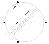
Solution 2
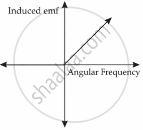
i. e = `1/2 B omega L^2`
So, e ∝ ω
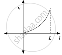
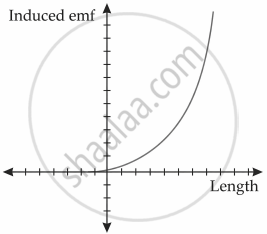
ii. e = `1/2 B omega L^2`
So, e ∝ L2
RELATED QUESTIONS
A cell of emf 'E' and internal resistance 'r' is connected across a variable load resistor R. Draw the plots of the terminal voltage V versus (i) R and (ii) the current I.
It is found that when R = 4 Ω, the current is 1 A and when R is increased to 9 Ω, the current reduces to 0.5 A. Find the values of the emf E and internal resistance r.
In a potentiometer arrangement, a cell of emf 1.25 V gives a balance point at 35.0 cm length of the wire. If the cell is replaced by another cell and the balance point shifts to 63.0 cm, what is the emf of the second cell?
The earth’s surface has a negative surface charge density of 10−9 C m−2. The potential difference of 400 kV between the top of the atmosphere and the surface results (due to the low conductivity of the lower atmosphere) in a current of only 1800 A over the entire globe. If there were no mechanism of sustaining atmospheric electric field, how much time (roughly) would be required to neutralise the earth’s surface? (This never happens in practice because there is a mechanism to replenish electric charges, namely the continual thunderstorms and lightning in different parts of the globe). (Radius of earth = 6.37 × 10⁶ m.)
A secondary cell after long use has an emf of 1.9 V and a large internal resistance of 380 Ω. What maximum current can be drawn from the cell? Could the cell drive the starting motor of a car?
Nichrome and copper wires of same length and same radius are connected in series. Current I is passed through them. Which wire gets heated up more? Justify your answer.
A cell of emf ‘E’ and internal resistance ‘r’ is connected across a variable resistor ‘R’. Plot a graph showing the variation of terminal potential ‘V’ with resistance R. Predict from the graph the condition under which ‘V’ becomes equal to ‘E’.
A battery of emf 100 V and a resistor of resistance 10 kΩ are joined in series. This system is used as a source to supply current to an external resistance R. If R is not greater than 100 Ω, the current through it is constant up to two significant digits.
Find its value. This is the basic principle of a constant-current source.
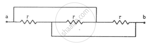
Find the equivalent resistance of the network shown in the figure between the points a and b.
Answer the following question.
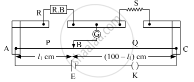
What is the end error in a meter bridge? How is it overcome? The resistances in the two arms of the metre bridge are R = Ω and S respectively. When the resistance S is shunted with equal resistance, the new balance length found to be 1.5 l1, where l2 is the initial balancing length. calculate the value of s.
If n cells each of emf e and internal resistance r are connected in parallel, then the total emf and internal resistance will be ______.
