Topics
Rotational Dynamics
- Rotational Dynamics
- Circular Motion and Its Characteristics
- Applications of Uniform Circular Motion
- Vertical Circular Motion
- Moment of Inertia as an Analogous Quantity for Mass
- Radius of Gyration
- Theorems of Perpendicular and Parallel Axes
- Angular Momentum or Moment of Linear Momentum
- Expression for Torque in Terms of Moment of Inertia
- Conservation of Angular Momentum
- Rolling Motion
- Overview: Rotational Dynamics
Circular Motion
- Angular Displacement
- Angular Velocity
- Angular Acceleration
- Angular Velocity and Its Relation with Linear Velocity
- Uniform Circular Motion (UCM)
- Radial Acceleration
- Dynamics of Uniform Circular Motion - Centripetal Force
- Centrifugal Forces
- Banking of Roads
- Vertical Circular Motion Due to Earth’s Gravitation
- Equation for Velocity and Energy at Different Positions of Vertical Circular Motion
- Kinematical Equations for Circular Motion in Analogy with Linear Motion.
Gravitation
- Newton’s Law of Gravitation
- Periodic Time
- Kepler’s Laws
- Binding Energy and Escape Velocity of a Satellite
- Weightlessness
- Variation of ‘G’ Due to Lattitude and Motion
- Variation in the Acceleration>Variation in Gravity with Altitude
- Communication satellite and its uses
- Composition of Two S.H.M.’S Having Same Period and Along Same Line
Mechanical Properties of Fluids
- Fluid and Its Properties
- Thrust and Pressure
- Pressure of liquid
- Pressure Exerted by a Liquid Column
- Atmospheric Pressure
- Gauge Pressure and Absolute Pressure
- Hydrostatic Paradox
- Pascal’s Law
- Application of Pascal’s Law
- Measurement of Atmospheric Pressure
- Mercury Barometer (Simple Barometer)
- Open Tube Manometer
- Surface Tension
- Molecular Theory of Surface Tension
- Surface Tension and Surface Energy
- Angle of Contact
- Effect of Impurity and Temperature on Surface Tension
- Excess Pressure Across the Free Surface of a Liquid
- Explanation of Formation of Drops and Bubbles
- Capillarity and Capillary Action
- Fluids in Motion
- Critical Velocity and Reynolds Number
- Viscous Force or Viscosity
- Stokes’ Law
- Terminal Velocity
- Continuous and Discontinuous Functions
- Bernoulli's Equation
- Applications of Bernoulli’s Equation
- Overview: Mechanical Properties of Fluids
Kinetic Theory of Gases and Radiation
- Gases and Its Characteristics
- Classification of Gases: Real Gases and Ideal Gases
- Mean Free Path
- Expression for Pressure Exerted by a Gas
- Root Mean Square (RMS) Speed
- Interpretation of Temperature in Kinetic Theory
- Law of Equipartition of Energy
- Specific Heat Capacity
- Absorption, Reflection, and Transmission of Heat Radiation
- Perfect Blackbody
- Emission of Heat Radiation
- Kirchhoff’s Law of Heat Radiation and Its Theoretical Proof
- Spectral Distribution of Blackbody Radiation
- Wien's Displacement Law
- Stefan-boltzmann Law of Radiation
- Overview: Kinetic Theory of Gases and Radiation
Angular Momentum
- Definition of M.I., K.E. of Rotating Body
- Rolling Motion
- Physical Significance of M.I (Moment of Inertia)
- Torque and Angular Momentum
- Theorems of Perpendicular and Parallel Axes
- M.I. of Some Regular Shaped Bodies About Specific Axes
Oscillations
- Periodic and Oscillatory Motion
- Simple Harmonic Motion (S.H.M.)
- Differential Equation of Linear S.H.M.
- Projection of U.C.M.(Uniform Circular Motion) on Any Diameter
- Phase of K.E (Kinetic Energy)
- K.E.(Kinetic Energy) and P.E.(Potential Energy) in S.H.M.
- Composition of Two S.H.M.’S Having Same Period and Along Same Line
- Some Systems Executing Simple Harmonic Motion
Thermodynamics
- Thermodynamics
- Thermal Equilibrium
- Measurement of Temperature
- Heat, Internal Energy and Work
- First Law of Thermodynamics
- Thermodynamic State Variables and Equation of State
- Thermodynamic Process
- Heat Engine
- Refrigerators and Heat Pumps
- Entropy and Second Law of Thermodynamics
- Carnot Cycle and Carnot Engine
- Overview: Thermodynamics
Elasticity
- Eneral Explanation of Elastic Property
- Stress and Strain
- Hooke’s Law
- Elastic Energy
- Elastic Constants and Their Relation
- Determination of ‘Y’
- Behaviour of Metal Wire Under Increasing Load
- Application of Elastic Behaviour of Materials
Oscillations
- Oscillations
- Explanation of Periodic Motion
- Linear Simple Harmonic Motion (S.H.M.)
- Differential Equation of Linear S.H.M.
- Acceleration (a), Velocity (v) and Displacement (x) of S.H.M.
- Amplitude (A), Period (T) and Frequency (N) of S.H.M.
- Reference Circle Method
- Phase in S.H.M.
- Graphical Representation of S.H.M.
- Composition of Two S.H.M.’S Having Same Period and Along Same Line
- The Energy of a Particle Performing S.H.M.
- Simple Pendulum
- Angular S.H.M. and It's Differential Equation
- Damped Oscillations
- Free Oscillations, Forced Oscillations and Resonance Oscillations
- Periodic and Oscillatory Motion
- Overview: Oscillations
Superposition of Waves
Surface Tension
- Molecular Theory of Surface Tension
- Surface Tension
- Capillarity and Capillary Action
- Effect of Impurity and Temperature on Surface Tension
Wave Optics
- Introduction to Wave Optics
- Nature of Light
- Light as a Wave
- Huygens Principle
- Reflection of Light at a Plane Surface
- Refraction of Light at a Plane Boundary Between Two Media
- Polarisation of Light
- Interference
- Diffraction of Light
- Resolving Power of Optical Instruments
- Overview: Wave Optics
Wave Motion
- Wave Motion Introduction
- Simple Harmonic Progressive Waves,
- Reflection of Transverse and Longitudinal Waves
- Change of Phase
- Principle of Superposition of Waves
- Formation of Beats
- Beats
Electrostatics
- Concept of Electrostatics
- Application of Gauss' Law
- Electric Potential and Potential Difference
- Electric Potential Due to a Point Charge
- Equipotential Surfaces
- Electrical Energy of Two Point Charges and of a Dipole in an Electrostatic Field
- Free and Bound Charges
- Combination of Capacitors
- Displacement Current
- Energy Stored in a Charged Capacitor
- Van De Graaff Generator
- Uniformly Charged Infinite Plane Sheet and Uniformly Charged Thin Spherical Shell (Field Inside and Outside)
- Overview: Electrostatics
Stationary Waves
- Study of Vibrations in a Finite Medium
- Formation of Stationary Waves on String
- Study of Vibrations of Air Columns
- Free and Forced Vibrations
- Forced Oscillations and Resonance
Kinetic Theory of Gases and Radiation
- Concept of an Ideal Gas
- Assumptions of Kinetic Theory of Gases
- Derivation for Pressure of a Gas
- Degrees of Freedom
- Derivation of Boyle’s Law
- Thermal Equilibrium
- First Law of Thermodynamics
- Heat Engine
- Temperature and Heat
- Qualitative Ideas of Black Body Radiation
- Wien's Displacement Law
- Green House Effect
- Stefan's Law
- Maxwell Distribution
- Specific Heat Capacities - Gases
- Law of Equipartition of Energy
Current Electricity
Wave Theory of Light
Magnetic Fields Due to Electric Current
- Magnetic Fields Due to Electric Current
- Magnetic force
- Cyclotron
- Helical Motion
- Magnetic Force on a Wire Carrying a Current
- Force on a Closed Circuit in a Magnetic Field
- Torque on a Current-Loop in a Uniform Magnetic Field
- Magnetic Dipole Moment
- Magnetic Potential Energy of a Dipole
- Magnetic Field Due to a Current-carrying Conductor: Biot-savart's Law
- Force of Attraction Between Two Long Parallel Wires
- Magnetic Field Produced by a Current in a Circular Arc of a Wire
- Applications of Biot-Savart's Law > Magnetic Field at the Axis of a Circular Current-carrying Loop
- Magnetic Lines for a Current Loop
- Ampere’s Circuital Law
- Applications of Ampere’s Circuital Law > Magnetic Field of a Toroidal Solenoid
- Overview: Magnetic Fields Due to Electric Current
Magnetic Materials
- Selection of Magnetic Materials
- Torque Acting on a Magnetic Dipole in a Uniform Magnetic Field
- Origin of Magnetism in Materials
- Magnetisation and Magnetic Intensity
- Magnetic Properties of Materials
- Classification of Magnetic Materials
- Hysteresis: Retentivity and Coercivity
- Permanent Magnet
- Magnetic Shielding
- Overview: Magnetic Materials
Interference and Diffraction
- Interference of Light
- Conditions for Producing Steady Interference Pattern
- Interference of Light Waves and Young’s Experiment
- Analytical Treatment of Interference Bands
- Measurement of Wavelength by Biprism Experiment
- Fraunhofer's Diffraction Due to a Single-slit
- Rayleigh’s Criterion
- Resolving Power of a Microscope and Telescope
- Interference Vs Diffraction
Electrostatics
- Mechanical Force on Unit Area of a Charged Conductor
- Energy Density of a Medium
- Concept of Condenser
- The Parallel Plate Capacitor
- Capacity of Parallel Plate Condenser
- Effect of Dielectric on Capacitance
- Energy of Charged Condenser
- Condensers in Series and Parallel,
- Van-deGraaff Generator
Electromagnetic Induction
- Introduction to Electromagnetic Induction
- Faraday's Laws of Electromagnetic Induction
- Lenz's Law
- Flux of a Vector Field
- Motional Electromotive Force (e.m.f.)
- Induced Emf in a Stationary Coil in a Changing Magnetic Field
- Generators
- Back Emf and Back Torque
- Induction and Energy Transfer
- Eddy Currents or Foucault Currents
- Self Inductance
- Energy Stored in a Magnetic Field
- Energy Density of a Magnetic Field
- Mutual Inductance
- Transformers
- Overview of Electromagnetic Induction
AC Circuits
- Introduction to Ac and Aс Circuits
- Values of Alternating Current
- Phasors
- AC Voltage Applied to a Resistor
- AC Voltage Applied to an Inductor
- AC Voltage Applied to a Capacitor
- AC Voltage Applied to a Series LCR Circuit
- Power in AC Circuit
- LC Oscillations
- Electric Resonance
- Sharpness of Resonance: Q Factor
- Choke Coil
- Overview: AC Circuits
Current Electricity
- Meter Bridge
Dual Nature of Radiation and Matter
Magnetic Effects of Electric Current
Magnetism
Structure of Atoms and Nuclei
- Structure of the Atom and Nucleus
- Thomson’s Atomic Model
- Geiger-marsden Experiment
- Rutherford’s Atomic Model
- Atomic Spectra
- Neils Bohr’s Model of an Atom
- Atomic Nucleus
- Constituents of a Nucleus
- Isotopes
- Atomic and Nuclear Masses
- Size of the Nucleus
- Mass Defect and Binding Energy
- Binding Energy Curve
- Forms of Energy > Nuclear Energy
- Nuclear Binding Energy
- Radioactive Decays
- Law of Radioactive Decay
- Overview: Structure of Atoms and Nuclei
Electromagnetic Inductions
- Introduction to Electromagnetic Induction
- Self Inductance
- Mutual Inductance
- Transformers
- Need for Displacement Current
- Coil Rotating in Uniform Magnetic Induction
- Alternating-Current Generator
- Reactance and Impedance
- LC Oscillations
- Inductance and Capacitance
- Resonant Circuits
- Power in AC Circuit
- Lenz’s Law and Conservation of Energy
Semiconductor Devices
Electrons and Photons
Atoms, Molecules and Nuclei
- Alpha-particle Scattering and Rutherford’s Nuclear Model of Atom
- Bohr’s Model for Hydrogen Atom
- Hydrogen Spectrum
- Atomic Masses and Composition of Nucleus
- Radioactivity
- Law of Radioactive Decay
- Atomic Mass, Mass - Energy Relation and Mass Defect
- Nuclear Binding Energy
- Nuclear Fusion
- de-Broglie Relation
- Wave Nature of Matter
- Wavelength of an Electron
- Davisson and Germer Experiment
- Continuous and Characteristics X-rays
- Mass Defect and Binding Energy
Semiconductors
- Energy Bands in Materials
- Extrinsic Semiconductor
- Applications of n-type and p-type Semiconductors
- Special Purpose P-n Junction Diodes
- Semiconductor Diode
- Voltage Regulator
- I-V Characteristics of Led
- Transistor and Characteristics of a Transistor
- Transistor as an Amplifier (Ce-configuration)
- Transistor as a Switch
- Oscillators
- Digital Electronics and Logic Gates
Communication Systems
Maharashtra State Board: Class 12
CISCE: Class 12
National Testing Agency: Class 12
Introduction
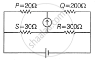
The Wheatstone Bridge is a circuit arrangement used to determine an unknown resistance with high accuracy by comparing it with known resistances.
It is based on the condition of null deflection, in which no current flows through the galvanometer.
Maharashtra State Board: Class 12
CISCE: Class 12
National Testing Agency: Class 12
Definition: Wheatstone Bridge
An arrangement of four resistors used to measure the resistance of one of them in terms of the other three, invented by Samuel Hunter Christie in 1833 and made famous by Sir Charles Wheatstone, is called a Wheatstone bridge.
Definition: Balance Condition
The condition of the Wheatstone bridge under which the galvanometer shows zero (null) deflection, i.e., Ig = 0, is called the balance condition of the bridge.
Formula: Balance Condition
Balance condition (when Ig = 0):
- AC → battery arm
- BD → galvanometer arm
- R4 → unknown resistance measured in terms of the other three.
National Testing Agency: Class 12
Circuit Structure
In the standard Wheatstone bridge arrangement:
- Four resistors form the four arms of the bridge.
- One diagonal acts as the battery arm.
- The other diagonal acts as the galvanometer arm.
- One of the resistors may be unknown and is calculated using the balance condition.
Standard Arm Labels
| Part | Role |
|---|---|
| AC | Battery arm |
| BD | Galvanometer arm |
| R4 | Unknown resistance in the given note format |
| Four side arms | Resistive branches used for balancing the bridge |
Maharashtra State Board: Class 12
CISCE: Class 12
National Testing Agency: Class 12
Working Principle
The bridge works on the principle that when the potentials at the two galvanometer junctions become equal, no current flows through the galvanometer.
At this stage, the bridge is balanced, and the ratio of resistances in one pair of arms equals the ratio in the other pair of arms.
Stepwise Logic
- Current from the battery divides into different branches of the bridge.
- The resistances are adjusted or chosen suitably.
- When the galvanometer shows zero deflection, the two junctions connected to it are at the same potential.
- The balance condition is then applied to calculate the unknown resistance.
Maharashtra State Board: Class 12
CISCE: Class 12
National Testing Agency: Class 12
Balanced vs Unbalanced Bridge
| Feature | Balanced Bridge | Unbalanced Bridge |
|---|---|---|
| Galvanometer current | Zero | Non-zero, so deflection occurs |
| Potential difference across the galvanometer | Zero | Non-zero |
| Formula applicability | The balance formula can be applied | The balance formula cannot be directly applied |
| Usefulness | Accurate resistance measurement | Indicates an imbalance in the network |
Maharashtra State Board: Class 12
CISCE: Class 12
National Testing Agency: Class 12
Key terms
| Term | Meaning |
|---|---|
| Null deflection | A condition in which the galvanometer shows zero deflection because no current flows through it |
| Balanced bridge | State in which the Wheatstone bridge satisfies the balance condition |
| Battery arm | Diagonal across which the battery is connected |
| Galvanometer arm | Diagonal across which the galvanometer is connected |
| Unknown resistance | The resistance is to be calculated using the bridge relation |
Example 1
Find the current through the galvanometer Ig.
Given
- AB = 100 Ω, BC = 10 Ω, CD = 5 Ω, DA = 60 Ω
- Galvanometer G = 15 Ω (across BD)
- Battery across AC = 10 V
Steps
- Assume: currents in main branches = I1 (AB – BC) and I2 (AD – DC), galvanometer current = Ig.
- Write KVL in loop ABD: get equation (3.65a) in I1, I2, Ig.
- Write KVL in loop BCD: get equation (3.65b).
- Write KVL in the outer loop with the battery: get equation (3.65c).
- Solve the three equations (eliminate I1, I2) to get Ig ≈ 4.87 mA.
Key idea: Unbalanced bridge → must use full KVL equations, not the balance formula.
CISCE: Class 12
Example 2
Find variable resistor Q and output voltage.
Given
- Bridge arms: P, Q, R, S (with given values)
- Q is variable, supply = 30 V
- The bridge is balanced
Steps
- Use the balance condition:
\[\frac {P}{Q}\] = \[\frac {R}{S}\] ⇒ Q = \[\frac {PS}{R}\]
Substitute values → Q ≈ 19.95 kΩ. - Find total resistance in Q‑branch: Rbranch = Q + other resistor.
- Current in that branch: I1 = 30 / Rbranch.
- Potential across Q: VAD = I1 × Q ≈ 24.58 V.
- Do the same for the other branch: find current I2, then VAB ≈ 24.58 V.
- Output voltage: Vout = VAB − VAD = 0 V (because the bridge is balanced).
Key idea: Balanced bridge → use ratio formula to get Q, and potentials at the two midpoints become equal, so output = 0.
Maharashtra State Board: Class 12
CISCE: Class 12
National Testing Agency: Class 12
Real-Life Analogy
The source material links the Wheatstone bridge to several practical and derived devices.
Main Applications
- Measurement of an unknown resistance.
- Working principle of the meter bridge.
- Use in post office box arrangements.
- Use in Carey-Foster’s bridge.
- Calibration-related applications for electrical measuring instruments such as voltmeters and ammeters.
A balanced Wheatstone bridge can be compared to a physical balance with equal moments on both sides. When both sides are perfectly matched, the indicator shows no tilt, just as the galvanometer shows no deflection.