Advertisements
Advertisements
Question
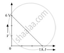
The plot of the variation of potential difference across a combination of three identical cells in series, versus current is shown below. What is the emf and internal resistance of each cell ?
Advertisements
Solution 1
Let E and r be the EMF and internal resistance of all cells respectively and e and r' be the EMF and internal resistance of each cell respectively.
As we know,
According to the definition of the terminal potential difference,
V = E − Ir
E is the EMF and r is the total internal resistance of the circuit.
I = 0 ⇒ V = E
From the graph we can see
E = 6 V
As there are three cells we can write,
E = 3 × e ⇒ e = 2 V
And, when, V = 0
⇒ E = Ir
`r=E/T=6/1=6Omega`
As per the question the cells are connected in the series, so we can write.
`r'=r/3=2Omega`
Solution 2
Since there are three cells connected in series, Total EMF = E1 + E2 + E3
We can observe from the graph that,
E1 + E2 + E3 = 6
3E = 6 (E = E1 = E2 = E3, as they are identical cells)
hence, The EMF of each cell is 2Volt.
Now, similarly, the internal resistance is also 2 Ohm for each, because in series combination of cells not only the Emf the internal resistance also gets added up.
APPEARS IN
RELATED QUESTIONS
A storage battery of emf 8.0 V and internal resistance 0.5 Ω is being charged by a 120 V dc supply using a series resistor of 15.5 Ω. What is the terminal voltage of the battery during charging? What is the purpose of having a series resistor in the charging circuit?
A battery of emf 100 V and a resistor of resistance 10 kΩ are joined in series. This system is used as a source to supply current to an external resistance R. If R is not greater than 100 Ω, the current through it is constant up to two significant digits.
Find its value. This is the basic principle of a constant-current source.
The temperatures of the junctions of a bismuth-silver thermocouple are maintained at 0°C and 0.001°C. Find the thermo-emf (Seebeck emf) developed. For bismuth-silver, a = − 46 × 10−6 V°C−1 and b = −0.48 × 10⁻⁶ V°C−2.
Answer the following question.
What is the end error in a meter bridge? How is it overcome? The resistances in the two arms of the metre bridge are R = Ω and S respectively. When the resistance S is shunted with equal resistance, the new balance length found to be 1.5 l1, where l2 is the initial balancing length. calculate the value of s.
A cell having an emf E and internal resistance r is connected across a variable external resistance R. As the resistance R is increased, the plot of potential difference V across R is given by ______.
If n cells each of emf e and internal resistance r are connected in parallel, then the total emf and internal resistance will be ______.
Two batteries of emf ε1 and ε2 (ε2 > ε1) and internal resistances r1 and r2 respectively are connected in parallel as shown in figure.

Study the two circuits shown in the figure below. The cells in the two circuits are identical to each other. The resistance of the load resistor R is the same in both circuits.

If the same current flows through the resistor R in both circuits, calculate the internal resistance of each cell in terms of the resistance of resistor R. Show your calculations.
The emf of a cell is defined as the work done in carrying a unit positive charge through which part of the circuit?
