Advertisements
Advertisements
Questions
Answer the following question.
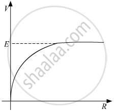
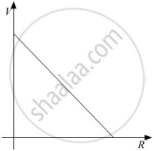
A cell of emf E and internal resistance r is connected across a variable resistor R. Plot the shape of graphs showing a variation of terminal voltage V with (i) R and (ii) circuit current I.
A cell emf of (E) and internal resistance. (r) is connected across a variable load resistance (R). Draw plots showing the variation of terminal voltage V with (i) R and (ii) the current (I) in the load.
Advertisements
Solution
Terminal Voltage V can be related to R by the following relation:
(i) `V = (ER)/(R+r)`
⇒ `V = (E)/(1+r/R)`
(ii) Terminal Voltage V can be related to I by the following relation:
V = E - IR
APPEARS IN
RELATED QUESTIONS
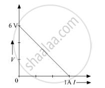
The plot of the variation of potential difference across a combination of three identical cells in series, versus current is shown below. What is the emf and internal resistance of each cell ?
A cell of emf 'E' and internal resistance 'r' is connected across a variable resistor 'R'. Plot a graph showing variation of terminal voltage 'V' of the cell versus the current 'I'. Using the plot, show how the emf of the cell and its internal resistance can be determined.
Two identical cells, each of emf E, having negligible internal resistance, are connected in parallel with each other across an external resistance R. What is the current through this resistance?
A cell of emf ‘E’ and internal resistance ‘r’ is connected across a variable resistor ‘R’. Plot a graph showing the variation of terminal potential ‘V’ with resistance R. Predict from the graph the condition under which ‘V’ becomes equal to ‘E’.
Can the potential difference across a battery be greater than its emf?
Consider N = n1n2 identical cells, each of emf ε and internal resistance r. Suppose n1 cells are joined in series to form a line and n2 such lines are connected in parallel.
The combination drives a current in an external resistance R. (a) Find the current in the external resistance. (b) Assuming that n1 and n2 can be continuously varied, find the relation between n1, n2, R and r for which the current in R is maximum.
Apply the first law of thermodynamics to a resistor carrying a current i. Identify which of the quantities ∆Q, ∆U and ∆W are zero, positive and negative.
Do the electrodes in an electrolytic cell have fixed polarity like a battery?
A cell of emf E is connected across an external resistance R. When current 'I' is drawn from the cell, the potential difference across the electrodes of the cell drops to V. The internal resistance 'r' of the cell is ______.
