Advertisements
Advertisements
Question
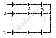
Consider N = n1n2 identical cells, each of emf ε and internal resistance r. Suppose n1 cells are joined in series to form a line and n2 such lines are connected in parallel.
The combination drives a current in an external resistance R. (a) Find the current in the external resistance. (b) Assuming that n1 and n2 can be continuously varied, find the relation between n1, n2, R and r for which the current in R is maximum.
Advertisements
Solution
(a)
Given:-
Emf of one cell = E
∴ Total e.m.f. of n1 cells in one row = n1E
Total emf of one row will be equal to the net emf across all the n2 rows because of parallel connection.
Total resistance in one row = n1r
Total resistance of n2 rows in parallel \[= \frac{n_1 r}{n_2}\]
Net resistance of the circuit = R + \[\frac{n_1 r}{n_2}\]
\[\therefore \text{Current, } I = \frac{n_1 E}{R + \frac{n_1 r}{n_2}} = \frac{n_1 n_2 E}{n_2 R + n_1 r}\]
(b) From (a),
\[I = \frac{n_1 n_2 E}{n_2 R + n_1 r}\]
For I to be maximum, (n1r + n2R) should be minimum
\[\Rightarrow \left( \sqrt{n_1 r} - \sqrt{n_2 R} \right)^2 + 2\sqrt{n_1 R n_2 r} = \min\]
It is minimum when
\[\sqrt{n_1 r} = \sqrt{n_2 R}\]
\[ n_1 r = n_2 R\]
∴ I is maximum when n1r = n2R .
APPEARS IN
RELATED QUESTIONS
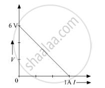
The plot of the variation of potential difference across a combination of three identical cells in series, versus current is shown below. What is the emf and internal resistance of each cell ?
A battery of emf 10 V and internal resistance 3 Ω is connected to a resistor. If the current in the circuit is 0.5 A, what is the resistance of the resistor? What is the terminal voltage of the battery when the circuit is closed?
A long straight current carrying wire passes normally through the centre of circular loop. If the current through the wire increases, will there be an induced emf in the loop? Justify.
A rectangular conductor LMNO is placed in a uniform magnetic field of 0.5 T. The field is directed perpendicular to the plane of the conductor. When the arm MN of length of 20 cm is moved towards left with a velocity of 10 ms−1, calculate the emf induced in the arm. Given the resistance of the arm to be 5 Ω (assuming that other arms are of negligible resistance) find the value of the current in the arm.

How many time constants will elapse before the power delivered by a battery drops to half of its maximum value in an RC circuit?
The temperatures of the junctions of a bismuth-silver thermocouple are maintained at 0°C and 0.001°C. Find the thermo-emf (Seebeck emf) developed. For bismuth-silver, a = − 46 × 10−6 V°C−1 and b = −0.48 × 10⁻⁶ V°C−2.
The internal resistance of a cell is the resistance of ______
Two batteries of emf ε1 and ε2 (ε2 > ε1) and internal resistances r1 and r2 respectively are connected in parallel as shown in figure.

A cell E1 of emf 6 V and internal resistance 2 Ω is connected with another cell E2 of emf 4 V and internal resistance 8 Ω (as shown in the figure). The potential difference across points X and Y is ______.

Three cells, each of emf E but internal resistances 2r, 3r and 6r are connected in parallel across a resistor R.
Obtain expressions for (i) current flowing in the circuit, and (ii) the terminal potential differences across the equivalent cell.
An ac generator generates an emf which is given by e = 311 sin (240 πt) V. Calculate:
- frequency of the emf.
- r.m.s. value of the emf.
Study the two circuits shown in the figure below. The cells in the two circuits are identical to each other. The resistance of the load resistor R is the same in both circuits.

If the same current flows through the resistor R in both circuits, calculate the internal resistance of each cell in terms of the resistance of resistor R. Show your calculations.
A wire of length ‘l’ and resistance 100 Ω is divided into 10 equal parts. The first 5 parts are connected in series while the next 5 parts are connected in parallel. The two combinations are again connected in series. The resistance of this final combination is ______.
When a cell is short-circuited (R = 0), the maximum current that can flow is:
During discharging of a cell, the current direction flows out of:
During charging of a cell, the current direction enters through:
During charging, electrical energy is converted to:
