Advertisements
Advertisements
प्रश्न
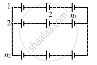
Consider N = n1n2 identical cells, each of emf ε and internal resistance r. Suppose n1 cells are joined in series to form a line and n2 such lines are connected in parallel.
The combination drives a current in an external resistance R. (a) Find the current in the external resistance. (b) Assuming that n1 and n2 can be continuously varied, find the relation between n1, n2, R and r for which the current in R is maximum.
Advertisements
उत्तर
(a)
Given:-
Emf of one cell = E
∴ Total e.m.f. of n1 cells in one row = n1E
Total emf of one row will be equal to the net emf across all the n2 rows because of parallel connection.
Total resistance in one row = n1r
Total resistance of n2 rows in parallel \[= \frac{n_1 r}{n_2}\]
Net resistance of the circuit = R + \[\frac{n_1 r}{n_2}\]
\[\therefore \text{Current, } I = \frac{n_1 E}{R + \frac{n_1 r}{n_2}} = \frac{n_1 n_2 E}{n_2 R + n_1 r}\]
(b) From (a),
\[I = \frac{n_1 n_2 E}{n_2 R + n_1 r}\]
For I to be maximum, (n1r + n2R) should be minimum
\[\Rightarrow \left( \sqrt{n_1 r} - \sqrt{n_2 R} \right)^2 + 2\sqrt{n_1 R n_2 r} = \min\]
It is minimum when
\[\sqrt{n_1 r} = \sqrt{n_2 R}\]
\[ n_1 r = n_2 R\]
∴ I is maximum when n1r = n2R .
APPEARS IN
संबंधित प्रश्न
Two cells of emfs 1.5 V and 2.0 V, having internal resistances 0.2 Ω and 0.3 Ω, respectively, are connected in parallel. Calculate the emf and internal resistance of the equivalent cell.
The plot of the variation of potential difference across a combination of three identical cells in series, versus current is shown below. What is the emf and internal resistance of each cell ?
In a potentiometer arrangement, a cell of emf 1.25 V gives a balance point at 35.0 cm length of the wire. If the cell is replaced by another cell and the balance point shifts to 63.0 cm, what is the emf of the second cell?
The earth’s surface has a negative surface charge density of 10−9 C m−2. The potential difference of 400 kV between the top of the atmosphere and the surface results (due to the low conductivity of the lower atmosphere) in a current of only 1800 A over the entire globe. If there were no mechanism of sustaining atmospheric electric field, how much time (roughly) would be required to neutralise the earth’s surface? (This never happens in practice because there is a mechanism to replenish electric charges, namely the continual thunderstorms and lightning in different parts of the globe). (Radius of earth = 6.37 × 10⁶ m.)
Six lead-acid types of secondary cells each of emf 2.0 V and internal resistance 0.015 Ω are joined in series to provide a supply to a resistance of 8.5 Ω. What are the current drawn from the supply and its terminal voltage?
Nichrome and copper wires of same length and same radius are connected in series. Current I is passed through them. Which wire gets heated up more? Justify your answer.
Plot a graph showing variation of voltage vs the current drawn from the cell. How can one get information from this plot about the emf of the cell and its internal resistance?
Two non-ideal batteries are connected in series. Consider the following statements:-
(A) The equivalent emf is larger than either of the two emfs.
(B) The equivalent internal resistance is smaller than either of the two internal resistances.
Do all thermocouples have a neutral temperature?
Do the electrodes in an electrolytic cell have fixed polarity like a battery?
The temperatures of the junctions of a bismuth-silver thermocouple are maintained at 0°C and 0.001°C. Find the thermo-emf (Seebeck emf) developed. For bismuth-silver, a = − 46 × 10−6 V°C−1 and b = −0.48 × 10⁻⁶ V°C−2.
A plate of area 10 cm2 is to be electroplated with copper (density 9000 kg m−3) to a thickness of 10 micrometres on both sides, using a cell of 12 V. Calculate the energy spent by the cell in the process of deposition. If this energy is used to heat 100 g of water, calculate the rise in the temperature of the water. ECE of copper = 3 × 10⁻⁷ kg C−1and specific heat capacity of water = 4200 J kg−1.
If n cells each of emf e and internal resistance r are connected in parallel, then the total emf and internal resistance will be ______.
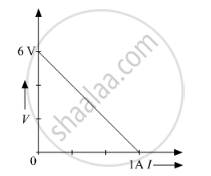
A straight line plot showing the terminal potential difference (V) of a cell as a function of current (I) drawn from it, is shown in the figure. The internal resistance of the cell would be then ______.

A cell of emf E and internal resistance r is connected across an external resistance R. Plot a graph showing the variation of P.D. across R, versus R.
A cell E1 of emf 6 V and internal resistance 2 Ω is connected with another cell E2 of emf 4 V and internal resistance 8 Ω (as shown in the figure). The potential difference across points X and Y is ______.

A cell of emf E is connected across an external resistance R. When current 'I' is drawn from the cell, the potential difference across the electrodes of the cell drops to V. The internal resistance 'r' of the cell is ______.
Three cells, each of emf E but internal resistances 2r, 3r and 6r are connected in parallel across a resistor R.
Obtain expressions for (i) current flowing in the circuit, and (ii) the terminal potential differences across the equivalent cell.
