Advertisements
Advertisements
प्रश्न
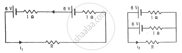
Find the value of i1/i2 in the following figure if (a) R = 0.1 Ω (b) R = 1 Ω and (c) R = 10 Ω. Note from your answers that in order to get more current from a combination of two batteries, they should be joined in parallel if the external resistance is small and in series if the external resistance is large, compared to the internal resistance.
Advertisements
उत्तर
(a) For R = 0.1 Ω
Applying KVL in the given circuit, we get:-
\[0 . 1 i_1 + 1 i_1 - 6 + 1 i_1 - 6 = 0\]
\[ \Rightarrow 0 . 1 i_1 + 1 i_1 + 1 i_1 = 12\]
\[ \Rightarrow i_1 = \frac{12}{\left( 2 . 1 \right)} = 5 . 71 A\]
Now, consider the given circuit.
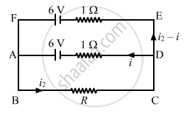
Applying KVL in the loop ABCDA, we get:-
\[0 . 1 i_2 + 1i - 6 = 0\]
\[ \Rightarrow 0 . 1 i_2 + i = 6\]
\[ \Rightarrow i = 6 - 0 . 1 i_2\]
Applying KVL in ADEFA, we get:-
\[i - 6 + 6 - \left( i_2 - i \right)1 = 0\]
\[ \Rightarrow i - i_2 + i = 0\]
\[ \Rightarrow 2i - i_2 = 0\]
\[ \Rightarrow 2\left[ 6 - 0 . 1 i_2 \right] - i_2 = 0\]
\[ \Rightarrow i_2 = 10 A\]
\[\therefore \frac{i_1}{i_2} = 0 . 571\]
(b) For R = 1 Ω
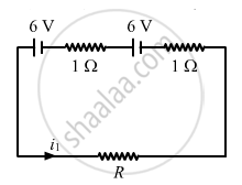
Applying KVL in the circuit given in figure 1, we get:-
\[1 i_1 + 1 . i_1 - 6 + i_1 - 6 = 0\]
\[ \Rightarrow 3 i_1 = 12\]
\[ \Rightarrow i_1 = 4\]
Now, for figure 2:-
Applying KVL in ABCDA, we get:-
\[i_2 + i - 6 = 0\]
\[ \Rightarrow i_2 + i = 6\]
Applying KVL in ADEFA, we get:-
\[i - 6 + 6 - \left( i_2 - i \right)1 = 0\]
\[ \Rightarrow i - i_2 + i = 0\]
\[ \Rightarrow 2i - i_2 = 0\]
\[ \Rightarrow 2\left[ 6 - i_2 \right] - i_2 = 0\]
\[ \Rightarrow 12 - 3 i_2 = 0\]
\[ \Rightarrow i_2 = 4 A\]
\[ \therefore \frac{i_1}{i_2} = 1\]
(c) For R = 10 Ω
Applying KVL in the circuit given in figure 1, we get:-
\[10 i_1 + 1 i_1 - 6 + 1 i_1 - 6 = 0\]
\[\Rightarrow 12 i_1 = 12\]
\[ \Rightarrow i_1 = 1\]
Now, for figure 2:-
Applying KVL in ABCDA, we get:-
\[10 i_2 + i - 6 = 0\]
\[ \Rightarrow i = 6 - 10 i_2\]
Applying KVL in ADEFA, we get:-
\[i - 6 + 6 - \left( i_2 - i \right)1 = 0\]
\[ \Rightarrow i - i_2 + i = 0\]
\[ \Rightarrow 2i - i_2 = 0\]
\[ \Rightarrow 2\left[ 6 - 10 i_2 \right] - i_2 = 0\]
\[ \Rightarrow 12 - 21 i_2 = 0\]
\[ \Rightarrow i_2 = 0 . 57 A\]
\[ \therefore \frac{i_1}{i_2} = 1 . 75\]
APPEARS IN
संबंधित प्रश्न
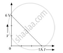
The plot of the variation of potential difference across a combination of three identical cells in series, versus current is shown below. What is the emf and internal resistance of each cell ?
Distinguish between emf and terminal voltage of a cell.
A cell of emf 'E' and internal resistance 'r' is connected across a variable resistor 'R'. Plot a graph showing variation of terminal voltage 'V' of the cell versus the current 'I'. Using the plot, show how the emf of the cell and its internal resistance can be determined.
The earth’s surface has a negative surface charge density of 10−9 C m−2. The potential difference of 400 kV between the top of the atmosphere and the surface results (due to the low conductivity of the lower atmosphere) in a current of only 1800 A over the entire globe. If there were no mechanism of sustaining atmospheric electric field, how much time (roughly) would be required to neutralise the earth’s surface? (This never happens in practice because there is a mechanism to replenish electric charges, namely the continual thunderstorms and lightning in different parts of the globe). (Radius of earth = 6.37 × 10⁶ m.)
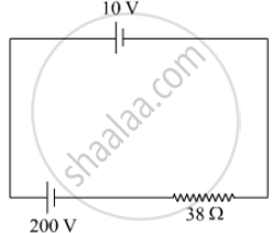
A 10 V cell of negligible internal resistance is connected in parallel across a battery of emf 200 V and internal resistance 38 Ω as shown in the figure. Find the value of current in the circuit.
In a potentiometer arrangement for determining the emf of a cell, the balance point of the cell in open circuit is 350 cm. When a resistance of 9 Ω is used in the external circuit of the cell, the balance point shifts to 300 cm. Determine the internal resistance of the cell.
A cell of emf ‘E’ and internal resistance ‘r’ draws a current ‘I’. Write the relation between terminal voltage ‘V’ in terms of E, I and r ?
Two non-ideal batteries are connected in parallel. Consider the following statements:-
(A) The equivalent emf is smaller than either of the two emfs.
(B) The equivalent internal resistance is smaller than either of the two internal resistances.
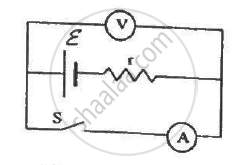
The following figure shows an arrangement to measure the emf ε and internal resistance r of a battery. The voltmeter has a very high resistance and the ammeter also has some resistance. The voltmeter reads 1.52 V when the switch S is open. When the switch is closed, the voltmeter reading drops to 1.45 V and the ammeter reads 1.0 A. Find the emf and the internal resistance of the battery.
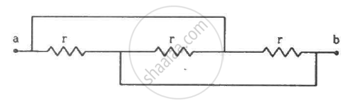
Find the equivalent resistance of the network shown in the figure between the points a and b.
Answer the following question.
A cell of emf E and internal resistance r is connected across a variable resistor R. Plot the shape of graphs showing a variation of terminal voltage V with (i) R and (ii) circuit current I.
A cell having an emf E and internal resistance r is connected across a variable external resistance R. As the resistance R is increased, the plot of potential difference V across R is given by ______.
If n cells each of emf e and internal resistance r are connected in parallel, then the total emf and internal resistance will be ______.
Five cells each of emf E and internal resistance r send the same amount of current through an external resistance R whether the cells are connected in parallel or in series. Then the ratio `("R"/"r")` is:
The internal resistance of a cell is the resistance of ______
A cell E1 of emf 6 V and internal resistance 2 Ω is connected with another cell E2 of emf 4 V and internal resistance 8 Ω (as shown in the figure). The potential difference across points X and Y is ______.

A battery of EMF 10V sets up a current of 1A when connected across a resistor of 8Ω. If the resistor is shunted by another 8Ω resistor, what would be the current in the circuit? (in A)
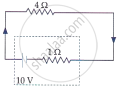
The terminal voltage of the battery, whose emf is 10 V and internal resistance 1 Ω, when connected through an external resistance of 4 Ω as shown in the figure is: