Advertisements
Advertisements
प्रश्न
In a potentiometer arrangement, a cell of emf 1.25 V gives a balance point at 35.0 cm length of the wire. If the cell is replaced by another cell and the balance point shifts to 63.0 cm, what is the emf of the second cell?
In a potentiometer experiment, a cell of emf 1.25 V gives a balance point at 35 cm mark of the wire. If this cell is replaced by another cell, the balance point is at 63 cm mark. Calculate the emf of the second cell.
Advertisements
उत्तर
Emf of the cell, E1 = 1.25 V
Balance point of the potentiometer, l1 = 35 cm
The cell is replaced by another cell of emf E2.
New balance point of the potentiometer, l2 = 63 cm
The balance condition is given by the relation,
`E_1/E_2 = I_1/I_2`
`E_2 = E_1 xx I_2/I_1`
= `1.25 xx 63/35`
= 2.25 V
Therefore, the emf of the second cell is 2.25 V.
संबंधित प्रश्न
A cell of emf 'E' and internal resistance 'r' is connected across a variable load resistor R. Draw the plots of the terminal voltage V versus (i) R and (ii) the current I.
It is found that when R = 4 Ω, the current is 1 A and when R is increased to 9 Ω, the current reduces to 0.5 A. Find the values of the emf E and internal resistance r.
The storage battery of a car has an emf of 12 V. If the internal resistance of the battery is 0.4 Ω, what is the maximum current that can be drawn from the battery?
A long straight current carrying wire passes normally through the centre of circular loop. If the current through the wire increases, will there be an induced emf in the loop? Justify.
In a potentiometer arrangement for determining the emf of a cell, the balance point of the cell in open circuit is 350 cm. When a resistance of 9 Ω is used in the external circuit of the cell, the balance point shifts to 300 cm. Determine the internal resistance of the cell.
Plot a graph showing variation of voltage vs the current drawn from the cell. How can one get information from this plot about the emf of the cell and its internal resistance?
Two identical cells, each of emf E, having negligible internal resistance, are connected in parallel with each other across an external resistance R. What is the current through this resistance?
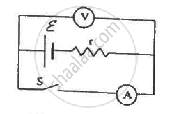
The following figure shows an arrangement to measure the emf ε and internal resistance r of a battery. The voltmeter has a very high resistance and the ammeter also has some resistance. The voltmeter reads 1.52 V when the switch S is open. When the switch is closed, the voltmeter reading drops to 1.45 V and the ammeter reads 1.0 A. Find the emf and the internal resistance of the battery.
Do all thermocouples have a neutral temperature?
Answer the following question.
A cell of emf E and internal resistance r is connected across a variable resistor R. Plot the shape of graphs showing a variation of terminal voltage V with (i) R and (ii) circuit current I.
A conductor of length ‘l’ is rotated about one of its ends at a constant angular speed ‘ω’ in a plane perpendicular to a uniform magnetic field B. Plot graphs to show variations of the emf induced across the ends of the conductor with
- angular speed ω and
- length of the conductor l.
A cell E1 of emf 6 V and internal resistance 2 Ω is connected with another cell E2 of emf 4 V and internal resistance 8 Ω (as shown in the figure). The potential difference across points X and Y is ______.

A block of metal is heated directly by dissipating power in the internal resistance of block. Because of temperature rise, the resistance increases exponentially with time and is given by R(t) = 0.5 e2t, where t is in second. The block is connected across a 110 V source and dissipates 7644 J heat energy over a certain period of time. This period of time is ______ × 10-1 sec (take ln 0.367 = -1).
Three cells, each of emf E but internal resistances 2r, 3r and 6r are connected in parallel across a resistor R.
Obtain expressions for (i) current flowing in the circuit, and (ii) the terminal potential differences across the equivalent cell.
An electric cell is a device that converts which form of energy into electrical energy?
Internal resistance of a cell is the resistance offered by which component?
When a cell is short-circuited (R = 0), the maximum current that can flow is:
During discharging of a cell, the current direction flows out of:
During discharging, chemical energy is converted to:
Internal resistance of a cell is affected by the surface area of electrodes. As surface area increases, internal resistance:
