Advertisements
Advertisements
प्रश्न
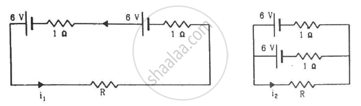
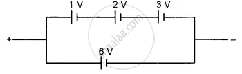
Find the value of i1/i2 in the following figure if (a) R = 0.1 Ω (b) R = 1 Ω and (c) R = 10 Ω. Note from your answers that in order to get more current from a combination of two batteries, they should be joined in parallel if the external resistance is small and in series if the external resistance is large, compared to the internal resistance.
Advertisements
उत्तर
(a) For R = 0.1 Ω
Applying KVL in the given circuit, we get:-
\[0 . 1 i_1 + 1 i_1 - 6 + 1 i_1 - 6 = 0\]
\[ \Rightarrow 0 . 1 i_1 + 1 i_1 + 1 i_1 = 12\]
\[ \Rightarrow i_1 = \frac{12}{\left( 2 . 1 \right)} = 5 . 71 A\]
Now, consider the given circuit.
Applying KVL in the loop ABCDA, we get:-
\[0 . 1 i_2 + 1i - 6 = 0\]
\[ \Rightarrow 0 . 1 i_2 + i = 6\]
\[ \Rightarrow i = 6 - 0 . 1 i_2\]
Applying KVL in ADEFA, we get:-
\[i - 6 + 6 - \left( i_2 - i \right)1 = 0\]
\[ \Rightarrow i - i_2 + i = 0\]
\[ \Rightarrow 2i - i_2 = 0\]
\[ \Rightarrow 2\left[ 6 - 0 . 1 i_2 \right] - i_2 = 0\]
\[ \Rightarrow i_2 = 10 A\]
\[\therefore \frac{i_1}{i_2} = 0 . 571\]
(b) For R = 1 Ω
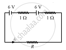
Applying KVL in the circuit given in figure 1, we get:-
\[1 i_1 + 1 . i_1 - 6 + i_1 - 6 = 0\]
\[ \Rightarrow 3 i_1 = 12\]
\[ \Rightarrow i_1 = 4\]
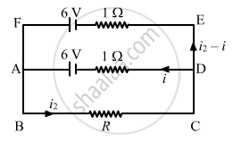
Now, for figure 2:-
Applying KVL in ABCDA, we get:-
\[i_2 + i - 6 = 0\]
\[ \Rightarrow i_2 + i = 6\]
Applying KVL in ADEFA, we get:-
\[i - 6 + 6 - \left( i_2 - i \right)1 = 0\]
\[ \Rightarrow i - i_2 + i = 0\]
\[ \Rightarrow 2i - i_2 = 0\]
\[ \Rightarrow 2\left[ 6 - i_2 \right] - i_2 = 0\]
\[ \Rightarrow 12 - 3 i_2 = 0\]
\[ \Rightarrow i_2 = 4 A\]
\[ \therefore \frac{i_1}{i_2} = 1\]
(c) For R = 10 Ω
Applying KVL in the circuit given in figure 1, we get:-
\[10 i_1 + 1 i_1 - 6 + 1 i_1 - 6 = 0\]
\[\Rightarrow 12 i_1 = 12\]
\[ \Rightarrow i_1 = 1\]
Now, for figure 2:-
Applying KVL in ABCDA, we get:-
\[10 i_2 + i - 6 = 0\]
\[ \Rightarrow i = 6 - 10 i_2\]
Applying KVL in ADEFA, we get:-
\[i - 6 + 6 - \left( i_2 - i \right)1 = 0\]
\[ \Rightarrow i - i_2 + i = 0\]
\[ \Rightarrow 2i - i_2 = 0\]
\[ \Rightarrow 2\left[ 6 - 10 i_2 \right] - i_2 = 0\]
\[ \Rightarrow 12 - 21 i_2 = 0\]
\[ \Rightarrow i_2 = 0 . 57 A\]
\[ \therefore \frac{i_1}{i_2} = 1 . 75\]
APPEARS IN
संबंधित प्रश्न
Two cells of emfs 1.5 V and 2.0 V, having internal resistances 0.2 Ω and 0.3 Ω, respectively, are connected in parallel. Calculate the emf and internal resistance of the equivalent cell.
Two identical cells of emf 1.5 V each joined in parallel, supply energy to an external circuit consisting of two resistances of 7 Ω each joined in parallel. A very high resistance voltmeter reads the terminal voltage of cells to be 1.4 V. Calculate the internal resistance of each cell.
The storage battery of a car has an emf of 12 V. If the internal resistance of the battery is 0.4 Ω, what is the maximum current that can be drawn from the battery?
A secondary cell after long use has an emf of 1.9 V and a large internal resistance of 380 Ω. What maximum current can be drawn from the cell? Could the cell drive the starting motor of a car?
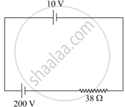
A 10 V cell of negligible internal resistance is connected in parallel across a battery of emf 200 V and internal resistance 38 Ω as shown in the figure. Find the value of current in the circuit.
In a potentiometer arrangement for determining the emf of a cell, the balance point of the cell in open circuit is 350 cm. When a resistance of 9 Ω is used in the external circuit of the cell, the balance point shifts to 300 cm. Determine the internal resistance of the cell.
A potentiometer wire of length 1.0 m has a resistance of 15 Ω. It is connected to a 5 V battery in series with a resistance of 5 Ω. Determine the emf of the primary cell which gives a balance point at 60 cm.
A cell of emf ‘E’ and internal resistance ‘r’ draws a current ‘I’. Write the relation between terminal voltage ‘V’ in terms of E, I and r ?
A cell of emf ‘E’ and internal resistance ‘r’ is connected across a variable resistor ‘R’. Plot a graph showing the variation of terminal potential ‘V’ with resistance R. Predict from the graph the condition under which ‘V’ becomes equal to ‘E’.
Apply the first law of thermodynamics to a resistor carrying a current i. Identify which of the quantities ∆Q, ∆U and ∆W are zero, positive and negative.
A plate of area 10 cm2 is to be electroplated with copper (density 9000 kg m−3) to a thickness of 10 micrometres on both sides, using a cell of 12 V. Calculate the energy spent by the cell in the process of deposition. If this energy is used to heat 100 g of water, calculate the rise in the temperature of the water. ECE of copper = 3 × 10⁻⁷ kg C−1and specific heat capacity of water = 4200 J kg−1.
Find the emf of the battery shown in the figure:
Answer the following question.
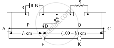
What is the end error in a meter bridge? How is it overcome? The resistances in the two arms of the metre bridge are R = Ω and S respectively. When the resistance S is shunted with equal resistance, the new balance length found to be 1.5 l1, where l2 is the initial balancing length. calculate the value of s.
The internal resistance of a cell is the resistance of ______
Three cells, each of emf E but internal resistances 2r, 3r and 6r are connected in parallel across a resistor R.
Obtain expressions for (i) current flowing in the circuit, and (ii) the terminal potential differences across the equivalent cell.
Study the two circuits shown in the figure below. The cells in the two circuits are identical to each other. The resistance of the load resistor R is the same in both circuits.

If the same current flows through the resistor R in both circuits, calculate the internal resistance of each cell in terms of the resistance of resistor R. Show your calculations.
