Advertisements
Advertisements
Question
Two batteries of emf ε1 and ε2 (ε2 > ε1) and internal resistances r1 and r2 respectively are connected in parallel as shown in figure.

Options
The equivalent emf εeq of the two cells is between ε1 and ε2, i.e. ε1 < εeq < ε2.
The equivalent emf εeq is smaller than ε1.
The εeq is given by εeq = ε1 + ε2 always.
εeq is independent of internal resistances r1 and r2.
Advertisements
Solution
The equivalent emf εeq of the two cells is between ε1 and ε2, i.e. ε1 < εeq < ε2.
Explanation:
The equivalent emf of this combination is given by
εeq = `(ε_1/r_1 + ε_1/r_2)/((1/r_1 + 1/r_2)) = (ε_1(1/r_1 + (ε_2/ε_1)/r_2))/((1/r_1 + 1/r_2)) = (ε_2((ε_1/ε_2)/r_1 + 1/r_2))/((1/r_1 + 1/r_2))`
As `ε_2/ε_1 > 1`
⇒ `((1/r_1 + (ε_2/r_1)/r_2))/((1/r_1 + 1/r_2)) > 1 or ε_(eq) > ε_1` also `ε_1/ε_2 < 1`
⇒ `(((ε_1/ε_2)/r_1 + 1/r_2))/((1/r_1 + 1/r_2)) < 1 or ε_(eq) < ε_1`
Hence ε1 < εeq < ε2.
APPEARS IN
RELATED QUESTIONS
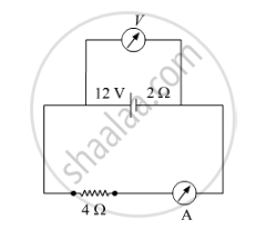
A battery of emf 12 V and internal resistance 2 Ω is connected to a 4 Ω resistor as shown in the figure.
(a) Show that a voltmeter when placed across the cell and across the resistor, in turn, gives the same reading.
(b) To record the voltage and the current in the circuit, why is voltmeter placed in parallel and ammeter in series in the circuit?
The storage battery of a car has an emf of 12 V. If the internal resistance of the battery is 0.4 Ω, what is the maximum current that can be drawn from the battery?
Nichrome and copper wires of same length and same radius are connected in series. Current I is passed through them. Which wire gets heated up more? Justify your answer.
A long straight current carrying wire passes normally through the centre of circular loop. If the current through the wire increases, will there be an induced emf in the loop? Justify.
In a potentiometer arrangement for determining the emf of a cell, the balance point of the cell in open circuit is 350 cm. When a resistance of 9 Ω is used in the external circuit of the cell, the balance point shifts to 300 cm. Determine the internal resistance of the cell.
Two identical cells, each of emf E, having negligible internal resistance, are connected in parallel with each other across an external resistance R. What is the current through this resistance?
A rectangular conductor LMNO is placed in a uniform magnetic field of 0.5 T. The field is directed perpendicular to the plane of the conductor. When the arm MN of length of 20 cm is moved towards left with a velocity of 10 ms−1, calculate the emf induced in the arm. Given the resistance of the arm to be 5 Ω (assuming that other arms are of negligible resistance) find the value of the current in the arm.

A cell of emf E and internal resistance r is connected to two external resistance R1 and R2 and a perfect ammeter. The current in the circuit is measured in four different situations:
(i) without any external resistance in the circuit
(ii) with resistance R1 only
(iii) with R1 and R2 in series combination
(iv) with R1 and R2 in parallel combination
The currents measured in the four cases are 0.42 A, 1.05 A, 1.4 A and 4.2 A, but not necessarily in the order. Identify the currents corresponding to the four cases mentioned above.
Can the potential difference across a battery be greater than its emf?
The temperatures of the junctions of a bismuth-silver thermocouple are maintained at 0°C and 0.001°C. Find the thermo-emf (Seebeck emf) developed. For bismuth-silver, a = − 46 × 10−6 V°C−1 and b = −0.48 × 10⁻⁶ V°C−2.
A conductor of length ‘l’ is rotated about one of its ends at a constant angular speed ‘ω’ in a plane perpendicular to a uniform magnetic field B. Plot graphs to show variations of the emf induced across the ends of the conductor with
- angular speed ω and
- length of the conductor l.
A straight line plot showing the terminal potential difference (V) of a cell as a function of current (I) drawn from it, is shown in the figure. The internal resistance of the cell would be then ______.

The internal resistance of a cell is the resistance of ______
A battery of EMF 10V sets up a current of 1A when connected across a resistor of 8Ω. If the resistor is shunted by another 8Ω resistor, what would be the current in the circuit? (in A)
A block of metal is heated directly by dissipating power in the internal resistance of block. Because of temperature rise, the resistance increases exponentially with time and is given by R(t) = 0.5 e2t, where t is in second. The block is connected across a 110 V source and dissipates 7644 J heat energy over a certain period of time. This period of time is ______ × 10-1 sec (take ln 0.367 = -1).
An ac generator generates an emf which is given by e = 311 sin (240 πt) V. Calculate:
- frequency of the emf.
- r.m.s. value of the emf.
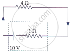
The terminal voltage of the battery, whose emf is 10 V and internal resistance 1 Ω, when connected through an external resistance of 4 Ω as shown in the figure is: