Advertisements
Advertisements
Question
When a p-n junction is reverse-biased, the current becomes almost constant at 25 µA. When it is forward-biased at 200 mV, a current of 75 µA is obtained. Find the magnitude of diffusion current when the diode is
(a) unbiased,
(b) reverse-biased at 200 mV and
(c) forward-biased at 200 mV.
Advertisements
Solution
Given:
Drift current (current under reverse bias), i1 = 25 µA
Forward bias voltage, V = 200 mV
Net current under forward bias, i2 = 75 µA
(a) When the p‒n junction is in unbiased condition, no net current flows across the junction.
i.e. Drift current = Diffusion current
∴ Diffusion current = 25 µA
(b) Under reverse bias, the built in the potential and applied voltage opposes the motion of the majority carriers across the junction.
Thus, the diffusion current becomes zero.
(c) Under forward bias, the voltage supports the motion of majority carriers across the junction.
Let the actual current be x.
So,
(x − Drift current) = Forward-biassed current
\[\Rightarrow x - 25 \mu \text{ A }= 75 \mu \text{A}\]
\[ \Rightarrow x = (75 + 25) \mu \text{ A }\]
\[ \Rightarrow x = 100 \mu \text{ A }\]
APPEARS IN
RELATED QUESTIONS
In an unbiased p-n junction, holes diffuse from the p-region to n-region because ______.
Explain briefly with the help of necessary diagrams, the forward biasing of a p-n junction diode. Also draw characteristic curves.
Explain briefly with the help of necessary diagrams, the reverse biasing of a p-n junction diode. Also draw characteristic curves.
A student wants to use two p-n junction diodes to convert alternating current into direct current. Draw the labelled circuit diagram she would use and explain how it works.
How is a zener diode fabricated so as to make it a special purpose diode? Draw I-V characteristics of zener diode and explain the significance of breakdown voltage.
Explain briefly, with the help of a circuit diagram, how a p-n junction diode works as a half wave rectifier.
If the two ends of a p-n junction are joined by a wire,
The diffusion current in a p-n junction is
Diffusion current in a p-n junction is greater than the drift current in magnitude
A hole diffuses from the p-side to the n-side in a p-n junction. This means that
In a p-n junction,
(a) new holes and conduction electrons are produced continuously throughout the material
(b) new holes and conduction electrons are produced continuously throughout the material except in the depletion region
(c) holes and conduction electrons recombine continuously throughout the material
(d) holes and conduction electrons recombine continuously throughout the material except in the depletion region.
The potential barrier existing across an unbiased p-n junction is 0.2 volt. What minimum kinetic energy a hole should have to diffuse from the p-side to the n-side if (a) the junction is unbiased, (b) the junction is forward-biased at 0.1 volt and (c) the junction is reverse-biased at 0.1 volt?
The drift current in a p-n junction is 20.0 µA. Estimate the number of electrons crossing a cross section per second in the depletion region.
What are the readings of the ammeters A1 and A2 shown in figure. Neglect the resistance of the meters.
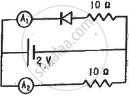
(Assume that the resistance of each diode is zero in forward bias and is infinity in reverse bias.)
Draw the current-voltage characteristics for the device show in figure between the terminals A and B.
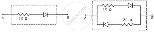
(Assume that the resistance of each diode is zero in forward bias and is infinity in reverse bias.)
Choose the correct option.
Current through a reverse-biased p-n junction increases abruptly at:
If in a p-n junction diode, a square input signal of 10 V is applied as shown Then the output signal across RL will be ______

The formation of the depletion region in a p-n junction diode is due to ______.
During the formation of a p-n junction ______.
