English

A Zener Diode is Fabricated by Heavily Doping Both P- and N- Sides of the Junction. Explain, Why?

Advertisements
Advertisements

Question

A zener diode is fabricated by heavily doping both p- and n- sides of the junction. Explain, why?

Advertisements

Solution

It is a heavily doped p-n junction. As a result, the depletion region formed is very thin and the electric field of the junction is extremely high even for a small reverse bias voltage.  

The I-V characteristics of a Zener diode are shown in the figure below:

shaalaa.com
  Is there an error in this question or solution?
2016-2017 (March) Delhi Set 2

RELATED QUESTIONS

In a p-n junction diode, the current I can be expressed as

I = `"I"_0 exp ("eV"/(2"k"_"BT") - 1)`

where I0 is called the reverse saturation current, V is the voltage across the diode and is positive for forward bias and negative for reverse bias, and I is the current through the diode, kBis the Boltzmann constant (8.6×10⁻⁵ eV/K) and T is the absolute temperature. If for a given diode I0 = 5 × 10⁻¹² A and T = 300 K, then

(a) What will be the forward current at a forward voltage of 0.6 V?

(b) What will be the increase in the current if the voltage across the diode is increased to 0.7 V?

(c) What is the dynamic resistance?

(d) What will be the current if reverse bias voltage changes from 1 V to 2 V?


Explain, with the help of a circuit diagram, the working of a photo-diode. Write briefly how it is used to detect the optical signals.


The diffusion current in a p-n junction is


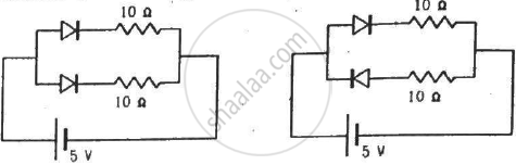
Two identical p-n junction may be connected in series with a battery in three ways. The potential difference across the two p-n junctions are equal in


In a p-n junction,
(a) new holes and conduction electrons are produced continuously throughout the material
(b) new holes and conduction electrons are produced continuously throughout the material except in the depletion region
(c) holes and conduction electrons recombine continuously throughout the material
(d) holes and conduction electrons recombine continuously throughout the material except in the depletion region.


The current−voltage characteristic of an ideal p-n junction diode is given by \[i =  i_0 ( e^{eV/KT}  - 1)\] where, the drift current i0 equals 10 µA. Take the temperature T to be 300 K. (a) Find the voltage V0 for which \[e^{eV/kT}  = 100 .\]One can neglect the term 1 for voltages greater than this value. (b) Find an expression for the dynamic resistance of the diode as a function of V for V > V0. (c) Find the voltage for which the dynamic resistance is 0.2 Ω.

(Use Planck constant h = 4.14 × 10⁻¹⁵ eV-s, Boltzmann constant k = 8·62 × 10-5 eV/K.)


Consider a p-n junction diode having the characteristic \[i -  i_0 ( e^{eV/kT}  - 1) \text{ where }  i_0  = 20\mu A\] . The diode is operated at T = 300 K . (a) Find the current through the diode when a voltage of 300 mV is applied across it in forward bias. (b) At what voltage does the current double?


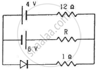
What are the readings of the ammeters A1 and A2 shown in figure. Neglect the resistance of the meters.

(Assume that the resistance of each diode is zero in forward bias and is infinity in reverse bias.)


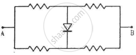
Draw the current-voltage characteristics for the device show in figure between the terminals A and B.

(Assume that the resistance of each diode is zero in forward bias and is infinity in reverse bias.)


The depletion layer in the p-n junction diode is caused by ______.


Share
Notifications

Englishहिंदीमराठी


      Forgot password?
Use app×