Advertisements
Advertisements
Question
A load resistor of 2kΩ is connected in the collector branch of an amplifier circuit using a transistor in common-emitter mode. The current gain β = 50. The input resistance of the transistor is 0.50 kΩ. If the input current is changed by 50µA. (a) by what amount does the output voltage change, (b) by what amount does the input voltage change and (c) what is the power gain?
Advertisements
Solution
Given:
Base current gain, \[\beta = 50\]
Change in base current, \[\delta I_b = 50 \mu A\]
Load resistance, \[R_L\] = 2 kΩ
Input resistance, \[R_i\] = 0.50 kΩ
(a) The change in output voltage is given by
\[V_0 = I_c \times R_L \]
\[ \because I_c = \beta \times I_b \]
\[ \therefore V_0 = \beta \times I_b \times R_L \]
\[ \Rightarrow V_0 = 50 \times 50 \mu A \times 2 k\Omega\]
\[ \Rightarrow V_0 = 5 V\]
(b) The change in input voltage is given by
\[\delta V_i = \delta l_b \times R_i \]
\[ \Rightarrow \delta V_i = 50 \times {10}^{- 6} \times 5 \times {10}^2 \]
\[ \Rightarrow \delta V_i = 25 \times {10}^{- 3} \]
\[ \Rightarrow \delta V_i = 25 \text{ mV}\]
(c) Power gain is given by
\[\beta^2 \times \frac{R_L}{R_i}\]
\[ \Rightarrow 2500 \times \frac{2}{0 . 5}\]
\[ \Rightarrow 2500 \times \frac{20}{5} = {10}^4\]
APPEARS IN
RELATED QUESTIONS
Write the two processes that take place in the formation of a p-n junction.
A zener diode is fabricated by heavily doping both p- and n- sides of the junction. Explain, why?
Mention the important considerations required while fabricating a p-n junction diode to be used as a Light Emitting Diode (LED). What should be the order of band gap of an LED if it is required to emit light in the visible range?
Explain, with the help of a circuit diagram, the working of n-p-n transistor as a common emitter amplifier.
If the two ends of a p-n junction are joined by a wire,
The diffusion current in a p-n junction is
Diffusion current in a p-n junction is greater than the drift current in magnitude
In a p-n junction with open ends,
(a) there is no systematic motion of charge carries
(b) holes and conduction electrons systematically go from the p-side to n-side and from the n-side to p-side respectively
(c) there is no net charge transfer between the two sides
(d) there is a constant electric field near the junction.
A semiconducting device is connected in a series circuit with a battery and a resistance. A current is found to pass through the circuit. If the polarity of the battery is reversed, the current drops to almost zero. the device may be
(a) an intrinsic semiconductor
(b) a p-type semiconductor
(c) an n-type semiconductor
(d) a p-n junction
The potential barrier existing across an unbiased p-n junction is 0.2 volt. What minimum kinetic energy a hole should have to diffuse from the p-side to the n-side if (a) the junction is unbiased, (b) the junction is forward-biased at 0.1 volt and (c) the junction is reverse-biased at 0.1 volt?
Consider a p-n junction diode having the characteristic \[i - i_0 ( e^{eV/kT} - 1) \text{ where } i_0 = 20\mu A\] . The diode is operated at T = 300 K . (a) Find the current through the diode when a voltage of 300 mV is applied across it in forward bias. (b) At what voltage does the current double?
Draw the current-voltage characteristics for the device show in figure between the terminals A and B.
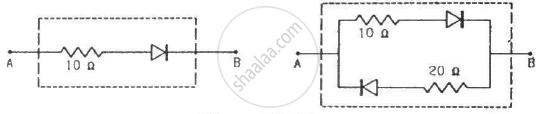
(Assume that the resistance of each diode is zero in forward bias and is infinity in reverse bias.)
Find the equivalent resistance of the network shown in figure between the points A and B.
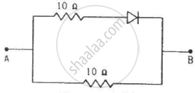
(Assume that the resistance of each diode is zero in forward bias and is infinity in reverse bias.)
When the base current in a transistor is changed from 30µA to 80µA, the collector current is changed from 1.0 mA to 3.5 mA. Find the current gain β.
Answer in detail.
Discuss the effect of external voltage on the width of depletion region of a p-n junction.
If in a p-n junction diode, a square input signal of 10 V is applied as shown Then the output signal across RL will be ______

The depletion layer in the p-n junction diode is caused by ______.
p-n junction diode is formed
Zener breakdown occurs in a p-n junction having p and n both:
