Topics
Electrostatics
Electric Charges and Fields
- Electric Charges
- Conductors and Insulators
- Properties of Electric Charge
- Coulomb’s Law
- Forces between Multiple Charges
- Electric Field
- Electric Field Due to a System of Charges
- Physical Significance of Electric Field
- Electric Field Lines
- Electric Flux
- Electric Dipole
- Dipole in a Uniform External Field
- Continuous Charge Distribution
- Gauss’s Law
- Application of Gauss' Law
Current Electricity
Electrostatic Potential and Capacitance
- Electric Potential and Potential Energy
- Electrostatic Potential
- Electric Potential Due to a Point Charge
- Potential Due to an Electric Dipole
- Potential due to a System of Charges
- Equipotential Surfaces
- Relation Between Electric Field and Electrostatic Potential
- Potential Energy of a System of Charges
- Potential Energy of a Single Charge
- Potential Energy of a System of Two Charges in an External Field
- Potential Energy of a Dipole in an External Field
- Electrostatics of Conductors
- Dielectrics and Polarisation
- Capacitors and Capacitance
- The Parallel Plate Capacitor
- Effect of Dielectric on Capacitance
- Combination of Capacitors
- Energy Stored in a Charged Capacitor
Magnetic Effects of Current and Magnetism
Current Electricity
- Electric Current
- Electric Currents in Conductors
- Ohm's Law
- Drift of Electrons and the Origin of Resistivity
- Mobility of Electrons
- Limitations of Ohm’s Law
- Resistivity of Various Materials
- Temperature Dependence of Resistivity
- Electrical Energy and Power in Conductors
- Cells, EMF, and Internal Resistance
- Cells in Series and in Parallel
- Kirchhoff’s Laws
- Wheatstone Bridge
Moving Charges and Magnetism
- Electromagnetism
- Magnetic force
- Motion in a Magnetic Field
- Magnetic Field Due to a Current-carrying Conductor: Biot-savart's Law
- Applications of Biot-Savart's Law > Magnetic Field at the Axis of a Circular Current-carrying Loop
- Ampere’s Circuital Law
- Solenoid
- Force Between Two Parallel Currents (Ampere’s Law)
- Torque on a Rectangular Current Loop in a Uniform Magnetic Field
- Circular Current Loop as a Magnetic Dipole
- Moving Coil Galvanometer
- Kirchhoff’s Laws
Electromagnetic Induction and Alternating Currents
Electromagnetic Waves
Magnetism and Matter
Optics
Electromagnetic Induction
Alternating Current
Dual Nature of Radiation and Matter
Atoms and Nuclei
Electromagnetic Waves
Electronic Devices
Ray Optics and Optical Instruments
- Ray Optics Or Geometrical Optics
- Reflection of Light by Spherical Mirrors
- Sign Convention for Reflection by Spherical Mirrors
- Focal Length of Spherical Mirrors
- Mirror Equation of Spherical Mirrors
- Refraction of Light
- Total Internal Reflection
- Applications of Total Internal Reflection
- Refraction at a Spherical Surfaces
- Refraction by a Lens
- Power of a Lens
- Combined Focal Length of Two Thin Lenses in Contact
- Refraction of Light through a Prism
- Introduction to Optical Instruments
- Microscope and it’s types
- Telescope
Wave Optics
- Introduction to Wave Optics
- Huygens Principle
- Refraction of a Plane Wave
- Refraction at a Rarer Medium
- Reflection of a Plane Wave by a Plane Surface
- Coherent and Incoherent Addition of Waves
- Interference of Light Waves and Young’s Experiment
- Diffraction of Light
- The Single Slit
- Seeing the Single Slit Diffraction Pattern
- Polarisation of Light
Communication Systems
Dual Nature of Radiation and Matter
- Understanding Dual Nature of Radiation and Matter
- Electron Emission
- Photoelectric Effect - Hertz’s Observations
- Photoelectric Effect - Hallwachs’ and Lenard’s Observations
- Experimental Study of Photoelectric Effect
- Effects of Intensity and Frequency on Photocurrent
- Photoelectric Effect and Wave Theory of Light
- Einstein’s Photoelectric Equation: Energy Quantum of Radiation
- Particle Nature of Light: The Photon
- Wave Nature of Matter
The Special Theory of Relativity
Atoms
Nuclei
Semiconductor Electronics - Materials, Devices and Simple Circuits
Communication Systems
- Detection of Amplitude Modulated Wave
- Production of Amplitude Modulated Wave
- Basic Terminology Used in Electronic Communication Systems
- Sinusoidal Waves
- Modulation and Its Necessity
- Amplitude Modulation (AM)
- Need for Modulation and Demodulation
- Satellite Communication
- Propagation of EM Waves
- Bandwidth of Transmission Medium
- Bandwidth of Signals
The Special Theory of Relativity
- The Special Theory of Relativity
- The Principle of Relativity
- Maxwell'S Laws
- Kinematical Consequences
- Dynamics at Large Velocity
- Energy and Momentum
- The Ultimate Speed
- Twin Paradox
Maharashtra State Board: Class 9, 11
CISCE: Class 12
Tamil Nadu Board of Secondary Education: Class 10, 12
National Testing Agency: Class 12
Introduction
Ohm's Law is a fundamental law of current electricity that relates potential difference, current, and resistance in a conductor. It states that for a metallic conductor under constant physical conditions, the current through it is directly proportional to the potential difference across its ends.
CISCE: Class 10, 12
Origin and Key Concepts
Ohm's Law was established by Georg Simon Ohm through experiments on conductors. The law is based on three core quantities:
- Potential Difference (V): Work done per unit charge.
- Current (I): Rate of flow of electric charge.
- Resistance (R): Opposition offered to the current.
Key Idea
-
If the conductor and its temperature remain unchanged, increasing the voltage increases the current in the same ratio.
Analogy
- Voltage is like water pressure.
- Current is like water flow.
- Resistance is like a narrow pipe opposing flow.
Maharashtra State Board: Class 9, 11
CISCE: Class 10, 12
Tamil Nadu Board of Secondary Education: Class 10, 12
National Testing Agency: Class 12
Definition: Ohm's Law
At constant temperature and other physical conditions, the current flowing through a conductor is directly proportional to the potential difference across its ends.
Maharashtra State Board: Class 9, 11
CISCE: Class 10, 12
Tamil Nadu Board of Secondary Education: Class 10, 12
National Testing Agency: Class 12
Formula: Ohm's Law
V ∝ I
V = IR
Other useful forms: I = \[\frac {V}{R}\] or R = \[\frac {V}{I}\]
CISCE: Class 10, 12
Law: Ohm's Law
Statement: Ohm’s Law
"The electric current flowing through a conductor is directly proportional to the potential difference across its ends, provided the temperature and other physical conditions of the conductor remain constant."
Mathematically,
I ∝ V or V = I R
where:
- V = Potential difference (in volts)
- I = Current (in amperes)
- R = Resistance of the conductor (in ohms, Ω)
Explanation:
When two conductors at different electric potentials are joined by a metallic wire, electrons flow from the conductor at a lower potential (excess electrons) to the one at a higher potential (deficit of electrons). This movement of electrons results in an electric current.
- The current continues to flow until both conductors reach the same potential.
- For continuous current flow, a constant potential difference must be maintained across the ends of the conductor (e.g., using a battery or power supply).
Derivation / Mathematical Proof:
From Ohm’s Law:
I ∝ V ⇒ \[\frac {V}{I}\] = constant
This constant is defined as the resistance (R) of the conductor. Therefore,
V = I R ---(1)
This is the mathematical form of Ohm’s Law.
Special Case:
If the current I = 1 A, then:
V = R
This implies that the resistance of a conductor is numerically equal to the potential difference across it when 1 ampere of current flows through it.
Conclusion:
Ohm's Law provides a fundamental relationship between voltage, current, and resistance in an electric circuit. It is widely used in the design and analysis of electrical and electronic systems.
Maharashtra State Board: Class 10
Applications
- It is used to calculate current, voltage, and resistance in electrical circuits.
- Helps determine power consumption using the formula P = VI.
- Used in circuit design to ensure proper voltage and current distribution.
- Helps in analysing resistivity, drift velocity, and electrical properties of materials.
- Essential in electrical safety calculations, such as determining fuse ratings and wire thickness for preventing overheating.
- Used in industries for troubleshooting electrical appliances and checking circuit functionality.
Experiment: Verification of Ohm's Law
Aim
To verify that the current through a conductor is directly proportional to the potential difference across it at constant temperature.
Apparatus Required
- A nichrome wire (or resistor) of known resistance
- An ammeter (to measure current) — connected in series
- A voltmeter (to measure potential difference) — connected in parallel across the resistor
- A rheostat (variable resistance) — to vary the current
- A battery or cells
- A plug key (switch)
- Connecting wires
Circuit Setup
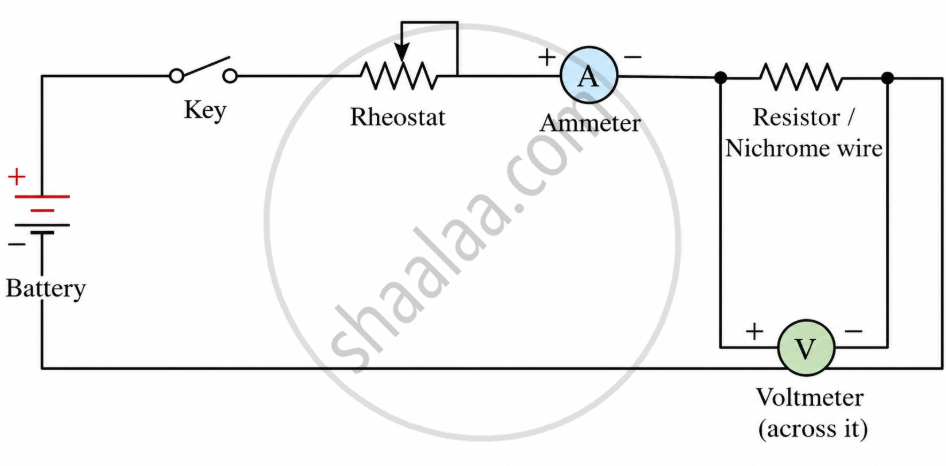
- The ammeter is placed in series so the same current passes through it.
- The voltmeter is placed in parallel, so it measures the exact potential difference across the resistor only.
- The rheostat is adjusted to change the current through the circuit step by step.
Procedure
- Set up the circuit as described above.
- Close the key to allow current to flow.
- Adjust the rheostat to a low current value.
- Note the ammeter reading (I) and the corresponding voltmeter reading (V).
- Increase the current step by step using the rheostat.
- Record 4–6 sets of V and I values in a table.
- For each set, calculate the ratio V/I.
Observation Table
| S. No. | Voltmeter Reading V (in volts) | Ammeter Reading I (in amperes) | Ratio V/I (in ohms) |
|---|---|---|---|
| 1 | V₁ | I₁ | V₁/I₁ |
| 2 | V₂ | I₂ | V₂/I₂ |
| 3 | V₃ | I₃ | V₃/I₃ |
Result: The ratio V/I remains nearly constant for all readings, which equals the resistance RR of the conductor.
Graph
- Plot V on the y-axis and I on the x-axis.
- The graph is a straight line passing through the origin.
- This straight-line nature confirms that V ∝ I, which is Ohm's Law.
- The slope of the line gives the resistance R:
Slope = \[\frac {V}{I}\] = R
A steeper slope means higher resistance; a gentler slope means lower resistance.
Conclusion
Since V/I = constant and the V-I graph is a straight line through the origin, the experiment confirms that:
The conductor obeys Ohm's Law under constant temperature conditions.
Precautions
- Do not leave the circuit closed for long — the wire heats up, changing resistance and invalidating results.
- Use the rheostat carefully to avoid sudden, large currents.
- Ensure the ammeter has low resistance and the voltmeter has high resistance for accurate readings.
Ohmic and Non-Ohmic Comparison
| Feature | Ohmic Conductor | Non-Ohmic Material |
|---|---|---|
| V-I relation | Linear | Non-linear |
| Resistance | Constant under fixed conditions | Variable |
| Graph | Straight line through origin | Curved |
| Examples | Metallic wire, resistor | Diode, thermistor |
Example 1
A current of 0.5 A flows through a resistor when 1.5 V is applied. Find resistance.
Answer: 3 Ω
Example 2
- What we know: The voltage (V) is 12 V and the resistance (R) is 24.
- The formula: Ohm's Law states that current (I) equals voltage divided by resistance: \[I = \frac{V}{R}\]
- The calculation: Plugging in the given numbers gives: \[I = \frac{12}{24} = 0.5\text{ A}\]
The current flowing through the resistor is 0.5 A (Amperes).
Maharashtra State Board: Class 9, 11
CISCE: Class 10, 12
Tamil Nadu Board of Secondary Education: Class 10, 12
National Testing Agency: Class 12
Real-Life Applications
- Electric appliances are designed using current-voltage-resistance relations.
- Electricians use Ohm's Law while checking wiring and circuit safety.
- Resistors in mobile chargers, LEDs, and electronic boards are selected using this law.