Advertisements
Advertisements
प्रश्न
Explain the equivalent resistance of a series resistor network.
Advertisements
उत्तर
When two or more resistors are connected end to end, they are said to be in series. The resistors could be simple resistors or bulbs or heating elements or other devices. Fig. (a) shows three resistors R1, R2 and R3 connected in series.
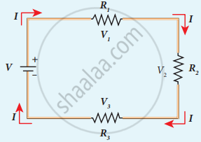
Three resistors in series
The amount of charge passing through resistor R1 must also pass through resistors R2 and R3 since the charges cannot accumulate anywhere in the circuit. Due to this reason, the current I passing through all the three resistors is the same. According to Ohm’s law, if same current pass through different resistors of different values, then the potential difference across each resistor must be different. Let V1, V2 and V3 be the potential difference (voltage) across each of the resistors R1, R2 and R3 respectively, then we can write V1 = IR1, V2 = IR2 and V3= IR3. But the total voltage V is equal to the sum of voltages across each resistor.
V = V1 + V2 + V3
= IR1 + IR2 + IR3 ….. (1)
V = I(R1 + R2 +R3)
V = I.RS …… (2)
where Rs = R1 + R2 R3 ……. (3)
When several resistances are connected in series, the total or equivalent resistance is the sum of the individual resistances as shown in the following figure.
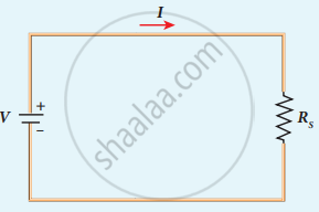
Equivalent resistance (RS) has the same current
APPEARS IN
संबंधित प्रश्न
Find the resistance of a conductor if 0.24 A current is passing through it and a potential difference of 24 V is applied across it.
How should the two resistances of 2 ohms each be connected so as to produce an equivalent resistance of 1 ohm?
Show by a diagram how two resistors R1 and R2 are joined in parallel. Obtain an expression for the total resistance of the combination.
Define the following:
Coulomb
A wire connected to a power supply of 230 V has power dissipation P1. Suppose the wire is cut into two equal pieces and connected parallel to the same power supply. In this case, power dissipation is P2. The ratio of `"P"_2/"P"_1` is
Obtain the macroscopic form of Ohm’s law from its microscopic form and discuss its limitation.
State Ohm's Law. Represent it mathematically.
Why should an ammeter have low resistance?
What is the nature of the graph obtained when potential difference is plotted against current for an Ohmic conductor?
Which formula is used with Ohm's Law to help determine power consumption in an electrical circuit?
