Advertisements
Advertisements
Question
Explain the equivalent resistance of a series resistor network.
Advertisements
Solution
When two or more resistors are connected end to end, they are said to be in series. The resistors could be simple resistors or bulbs or heating elements or other devices. Fig. (a) shows three resistors R1, R2 and R3 connected in series.
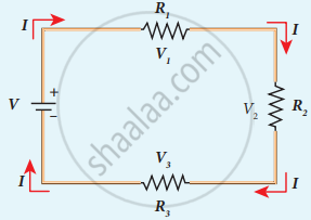
Three resistors in series
The amount of charge passing through resistor R1 must also pass through resistors R2 and R3 since the charges cannot accumulate anywhere in the circuit. Due to this reason, the current I passing through all the three resistors is the same. According to Ohm’s law, if same current pass through different resistors of different values, then the potential difference across each resistor must be different. Let V1, V2 and V3 be the potential difference (voltage) across each of the resistors R1, R2 and R3 respectively, then we can write V1 = IR1, V2 = IR2 and V3= IR3. But the total voltage V is equal to the sum of voltages across each resistor.
V = V1 + V2 + V3
= IR1 + IR2 + IR3 ….. (1)
V = I(R1 + R2 +R3)
V = I.RS …… (2)
where Rs = R1 + R2 R3 ……. (3)
When several resistances are connected in series, the total or equivalent resistance is the sum of the individual resistances as shown in the following figure.
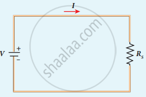
Equivalent resistance (RS) has the same current
APPEARS IN
RELATED QUESTIONS
What will be the change in the current if the potential difference is kept constant and the resistance of the circuit is made four times?
- It will remain unchanged.
- It will become four times.
- It will become one-fourth.
- It will become half.
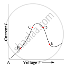
Graph showing the variation of current versus voltage for a material Ga As is shown in the figure. Identify the region of
(i) negative resistance
(ii) where Ohm's law is obeyed.
An electric bulb draws 1.2 A current at 6.0 V. Find the resistance of filament of bulb while glowing.
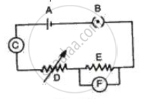
Fig. represents the circuit used for the verification of ohm's law. Label the different parts from A and F. State the function of each.
State and define Ohm’s law.
The heat produced by a 100 w heater in 2 minute is equal to
The circuit depicted in the figure is employed for studying Ohm’s Law. Instead of using a standard resistor, a student opts for a glass tube filled with mercury (tube 1), connected to the circuit through two electrodes, E1 and E2. He records the readings of the ammeter and voltmeter, thereby calculating the resistance. The student repeats the experiment by substituting tube 1 with tube 2, where the same amount of mercury fills tube 2.
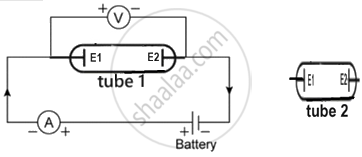
Neglecting internal resistance of the cell use (> or < or =) to compare:
- the resistance in both the cases.
- the voltmeter readings in both the cases.
- the specific resistance in both the cases.
A current of 3.2 mA flows through a conductor. If charge on an electron is −1.6 × 10⁻¹⁹ coulomb, find the number of electrons that will pass each second through the cross section of that conductor.
The mathematical form of Ohm's Law is:
