Advertisements
Advertisements
Question
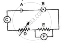
Fig. represents the circuit used for the verification of ohm's law. Label the different parts from A and F. State the function of each.
Advertisements
Solution
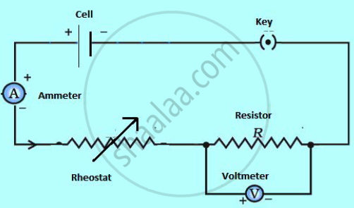
Functions:
(A) Cell- It provides the potential difference in the circuit.
(B) Key- It serves as a switch in the circuit. It supplies or cuts off current as required.
(C) Ammeter - It measures the current in the circuit.
(D) Rheostat- It helps to change the resistance of the circuit without changing its voltage.
(E) Resistor- It provides a constant resistance in the circuit.
(F) Voltmeter - It measure the potential drop across the resistor.
APPEARS IN
RELATED QUESTIONS
What will be the change in the current if the potential difference is kept constant and the resistance of the circuit is made four times?
- It will remain unchanged.
- It will become four times.
- It will become one-fourth.
- It will become half.
Why are coils of electric toasters and electric irons made of an alloy rather than a pure metal?
The relationship between the potential difference and the current in a conductor is stated in the form of a law.
1) Name the law.
2) What does the slope of V-I graph for a conductor represent?
3) Name the material used for making the connecting wire.
What is an Ohmic resistor?
Define temperature coefficient of resistance.
The variable resistance is called ____________.
The temperature of a conductor is increased. The graph best showing the variation of its resistance is:

Calculate the total resistance of the circuit and find the total current in the circuit.
A current of 2amp flowing through a conductor produced 80 joule of heat in 10 sec. The resistance of the conductor is:-
The circuit depicted in the figure is employed for studying Ohm’s Law. Instead of using a standard resistor, a student opts for a glass tube filled with mercury (tube 1), connected to the circuit through two electrodes, E1 and E2. He records the readings of the ammeter and voltmeter, thereby calculating the resistance. The student repeats the experiment by substituting tube 1 with tube 2, where the same amount of mercury fills tube 2.
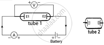
Neglecting internal resistance of the cell use (> or < or =) to compare:
- the resistance in both the cases.
- the voltmeter readings in both the cases.
- the specific resistance in both the cases.
