Advertisements
Advertisements
प्रश्न
The current−voltage characteristic of an ideal p-n junction diode is given by \[i = i_0 ( e^{eV/KT} - 1)\] where, the drift current i0 equals 10 µA. Take the temperature T to be 300 K. (a) Find the voltage V0 for which \[e^{eV/kT} = 100 .\]One can neglect the term 1 for voltages greater than this value. (b) Find an expression for the dynamic resistance of the diode as a function of V for V > V0. (c) Find the voltage for which the dynamic resistance is 0.2 Ω.
(Use Planck constant h = 4.14 × 10⁻¹⁵ eV-s, Boltzmann constant k = 8·62 × 10-5 eV/K.)
Advertisements
उत्तर
(a) The current‒voltage relationship of a diode is given by
\[i = i_0 ( e^{eV/kT - 1} )\]
For a large value of voltage, 1 can be neglected.
\[i \approx i_0 e^{eV/kT}\]
Again, we need to find the voltage at which
\[e^{eV/kT} = 100\]
\[\Rightarrow \frac{eV}{kT} = \text{ln }100\]
\[ \Rightarrow V = \frac{\text{ ln }100 \times \text{ kT }}{e}\]
\[ \Rightarrow V = \frac{2 . 303 \times \log 100 \times 8 . 62 \times {10}^{- 5} \times 300}{e}\]
\[ \Rightarrow V=0.12\] V
(b) Given:-
\[i = i_0 ( e^{eV/kT - 1} ) ...........(1)\]
We know that the dynamic resistance of a diode is the rate of change of voltage w.r.t. current.
i.e.
\[R = \frac{d V}{\text{d i}}\]
As the exponential factor dominates the factor of 1, we can neglect this factor.
Now, on differentiating eq. (1) w.r.t. V, we get
\[\frac{\text{di}}{\text{dV}} = i_0 \frac{e}{kT} e^{eV/kT} \]
\[ \Rightarrow \frac{1}{R} = \frac{e i_0}{kT} e^{eV/kT} \]
\[ \Rightarrow R = \frac{kT}{e i_0} e^{- eV/kT} ............(2)\]
(c) Given:-
R = 2 Ω
On substituting this value in eq. (2), we get
\[2 = \frac{8 . 62 \times {10}^{- 5} \times 300}{e \times 10 \times {10}^{- 6}} e^{- eV/8 . 62 \times {10}^{- 5} \times 300} \]
\[ \Rightarrow V = 0 . 25 \] V
APPEARS IN
संबंधित प्रश्न
A student wants to use two p-n junction diodes to convert alternating current into direct current. Draw the labelled circuit diagram she would use and explain how it works.
Explain, with the help of a circuit diagram, the working of a photo-diode. Write briefly how it is used to detect the optical signals.
Mention the important considerations required while fabricating a p-n junction diode to be used as a Light Emitting Diode (LED). What should be the order of band gap of an LED if it is required to emit light in the visible range?
If the two ends of a p-n junction are joined by a wire,
The drift current in a p-n junction is
The potential barrier existing across an unbiased p-n junction is 0.2 volt. What minimum kinetic energy a hole should have to diffuse from the p-side to the n-side if (a) the junction is unbiased, (b) the junction is forward-biased at 0.1 volt and (c) the junction is reverse-biased at 0.1 volt?
In a p-n junction, a potential barrier of 250 meV exists across the junction. A hole with a kinetic energy of 300 meV approaches the junction. Find the kinetic energy of the hole when it crosses the junction if the hole approached the junction (a) from the p-side and (b) from the n-side.
When a p-n junction is reverse-biased, the current becomes almost constant at 25 µA. When it is forward-biased at 200 mV, a current of 75 µA is obtained. Find the magnitude of diffusion current when the diode is
(a) unbiased,
(b) reverse-biased at 200 mV and
(c) forward-biased at 200 mV.
Consider a p-n junction diode having the characteristic \[i - i_0 ( e^{eV/kT} - 1) \text{ where } i_0 = 20\mu A\] . The diode is operated at T = 300 K . (a) Find the current through the diode when a voltage of 300 mV is applied across it in forward bias. (b) At what voltage does the current double?
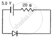
Calculate the current through the circuit and the potential difference across the diode shown in figure. The drift current for the diode is 20 µA.
Find the currents through the resistance in the circuits shown in figure.
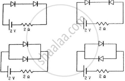
(Assume that the resistance of each diode is zero in forward bias and is infinity in reverse bias.)
Draw the current-voltage characteristics for the device show in figure between the terminals A and B.
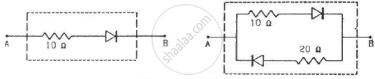
(Assume that the resistance of each diode is zero in forward bias and is infinity in reverse bias.)
Find the equivalent resistance of the network shown in figure between the points A and B.
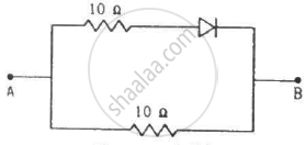
(Assume that the resistance of each diode is zero in forward bias and is infinity in reverse bias.)
A diode, a resistor and a 50 Hz AC source are connected in series. The number of current pulses per second through the resistor is __________ .
Choose the correct option.
Current through a reverse-biased p-n junction increases abruptly at:
If in a p-n junction diode, a square input signal of 10 V is applied as shown Then the output signal across RL will be ______

In a semiconductor diode, the barrier potential offers opposition to only ______.
p-n junction diode is formed
Zener breakdown occurs in a p-n junction having p and n both:
In p-n junction diode ______.
