Advertisements
Advertisements
प्रश्न
The drift current in a p-n junction is 20.0 µA. Estimate the number of electrons crossing a cross section per second in the depletion region.
Advertisements
उत्तर
Given:
Drift current, id = 20 µA = 20 × 10−6 A
Both holes and electrons are moving and contributing to the current flow.
We know that current is the rate of the flow of charge.
Thus, we need to find the number of electrons crossing unit area per second.
Now,
t = 1 s
\[i_d = \frac{Q}{T}\]
\[ \because T = 1 \]s
\[ \therefore i_d = Q = \]ne
\[ \Rightarrow n = \frac{i_d}{e}\]
So, the total number of charge carriers crossing the depletion region is given by
\[n = \frac{20 \times {10}^{- 6}}{2 \times 1 . 6 \times {10}^{- 19}}\]
\[ \Rightarrow n = 6 . 25 \times {10}^{13}\]
Also, the number of electrons crossing the depletion region is given by
\[n_e = \frac{n}{2} = \frac{6 . 25 \times {10}^{13}}{2}\]
\[ \Rightarrow n_e = 3 . 1 \times {10}^{13}\]
APPEARS IN
संबंधित प्रश्न
Explain briefly with the help of necessary diagrams, the forward biasing of a p-n junction diode. Also draw characteristic curves.
A student wants to use two p-n junction diodes to convert alternating current into direct current. Draw the labelled circuit diagram she would use and explain how it works.
Mention the important considerations required while fabricating a p-n junction diode to be used as a Light Emitting Diode (LED). What should be the order of band gap of an LED if it is required to emit light in the visible range?
A hole diffuses from the p-side to the n-side in a p-n junction. This means that
In a p-n junction with open ends,
(a) there is no systematic motion of charge carries
(b) holes and conduction electrons systematically go from the p-side to n-side and from the n-side to p-side respectively
(c) there is no net charge transfer between the two sides
(d) there is a constant electric field near the junction.
A semiconducting device is connected in a series circuit with a battery and a resistance. A current is found to pass through the circuit. If the polarity of the battery is reversed, the current drops to almost zero. the device may be
(a) an intrinsic semiconductor
(b) a p-type semiconductor
(c) an n-type semiconductor
(d) a p-n junction
In a p.n junction, the depletion region is 400 nm wide and an electric field of 5 × 10⁵ V m−1 exists in it. (a) Find the height of the potential barrier. (b) What should be the minimum kinetic energy of a conduction electron which can diffuse from the n-side to the p-side?
Find the current through the resistance R in figure if (a) R = 12Ω (b) R = 48Ω.
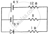
(Assume that the resistance of each diode is zero in forward bias and is infinity in reverse bias.)
Draw the current-voltage characteristics for the device show in figure between the terminals A and B.
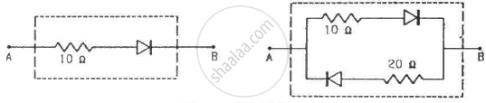
(Assume that the resistance of each diode is zero in forward bias and is infinity in reverse bias.)
When the base current in a transistor is changed from 30µA to 80µA, the collector current is changed from 1.0 mA to 3.5 mA. Find the current gain β.
An AC source is connected to a diode and a resistor in series. Is the current thorough the resistor AC or DC?
Answer in detail.
Discuss the effect of external voltage on the width of depletion region of a p-n junction.
In a semiconductor diode, the barrier potential offers opposition to only ______.
p-n junction diode is formed
Zener breakdown occurs in a p-n junction having p and n both:
The formation of the depletion region in a p-n junction diode is due to ______.
During the formation of a p-n junction ______.
For an ideal diode, in forward and reverse biased condition the resistance is respectively ______.
In p-n junction diode ______.
