Advertisements
Advertisements
प्रश्न
When a p-type impurity is doped in a semiconductor, a large number of holes are created, This does not make the semiconductor charged. But when holes diffuse from the p-side to the n-side in a p-n junction, the n-side gets positively charged. Explain.
Advertisements
उत्तर
A p-type semiconductor is formed by doping a group 13 element with group 14 element (Si or Ge). As the group 13 element has only 3 electrons in its valence shell and the group 14 element has 4 electrons in its valence shell, when the group 13 element, say, Al, replaces one Si in the silicon crystal, only 3 covalent bonds are formed by it. And the fourth covalent bond is left in need of one electron. So, it creates a hole. Since the atom as a whole is electriclly neutral, the p-type semiconductor is also neutral.
In a p‒n junction, when the diffusion of holes takes place across the junction because of the difference in the concentration of charge carriers from p to n sides, these holes neutralise some of the electrons on the n side. So, the atom attached with that electron becomes one electron deficient and hence positively charged. This makes the n side of the p‒n junction positively charged and the p side of the p‒n junction negatively charged.
APPEARS IN
संबंधित प्रश्न
In an unbiased p-n junction, holes diffuse from the p-region to n-region because ______.
Write the two processes that take place in the formation of a p-n junction.
Explain, with the help of a circuit diagram, the working of n-p-n transistor as a common emitter amplifier.
If the two ends of a p-n junction are joined by a wire,
The current−voltage characteristic of an ideal p-n junction diode is given by \[i = i_0 ( e^{eV/KT} - 1)\] where, the drift current i0 equals 10 µA. Take the temperature T to be 300 K. (a) Find the voltage V0 for which \[e^{eV/kT} = 100 .\]One can neglect the term 1 for voltages greater than this value. (b) Find an expression for the dynamic resistance of the diode as a function of V for V > V0. (c) Find the voltage for which the dynamic resistance is 0.2 Ω.
(Use Planck constant h = 4.14 × 10⁻¹⁵ eV-s, Boltzmann constant k = 8·62 × 10-5 eV/K.)
Find the currents through the resistance in the circuits shown in figure.
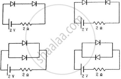
(Assume that the resistance of each diode is zero in forward bias and is infinity in reverse bias.)
What are the readings of the ammeters A1 and A2 shown in figure. Neglect the resistance of the meters.
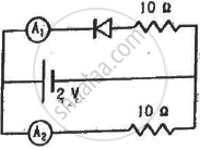
(Assume that the resistance of each diode is zero in forward bias and is infinity in reverse bias.)
Find the current through the battery in each of the circuits shown in figure.
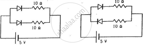
(Assume that the resistance of each diode is zero in forward bias and is infinity in reverse bias.)
Draw the current-voltage characteristics for the device show in figure between the terminals A and B.
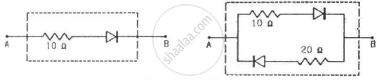
(Assume that the resistance of each diode is zero in forward bias and is infinity in reverse bias.)
When the base current in a transistor is changed from 30µA to 80µA, the collector current is changed from 1.0 mA to 3.5 mA. Find the current gain β.
If in a p-n junction diode, a square input signal of 10 V is applied as shown Then the output signal across RL will be ______

In a semiconductor diode, the barrier potential offers opposition to only ______.
Zener breakdown occurs in a p-n junction having p and n both:
Diode and resistance are connected as shown in figure. Out of the following statements which one is TRUE?
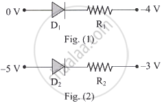
What is drift?
What is static resistance?
What role do diodes perform in electronic switching?
What is the approximate knee voltage for germanium?
Which formula gives the static resistance of a diode?
