Advertisements
Advertisements
Question
Name the following diagram and explain the concept behind it.
Advertisements
Solution
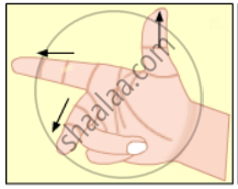
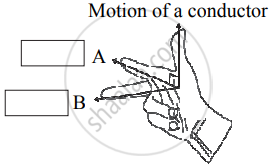
Name: Fleming’s right-hand rule
Concept: It represents Fleming’s right-hand rule used for finding the direction of the induced current with respect to the directions of the magnetic field and motion of the conductor.
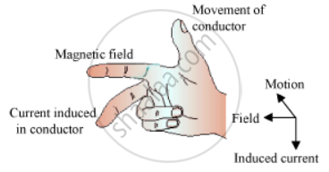
The direction of the current induced in a conductor can be obtained by holding the thumb, the index finger, and the middle finger of your right hand mutually perpendicular to each other. In this situation, the thumb indicates the direction of the motion of the conductor, the index finger points along the magnetic field, and the middle finger points along the current induced in the conductor.
APPEARS IN
RELATED QUESTIONS
State Fleming’s right-hand rule.
State three differences between direct current and alternating current.
The phenomenon of electromagnetic induction is
Prove theoretically (electromagnetic induction) `e = (dphi)/(dt)`
An emf of 2V is induced in a coil when the current in it is changed from 0A to 10A in 0·40 sec. Find the coefficient of self-inductance of the coil.
When an electric current is passed through any wire, a magnetic field is produced around it. Then why an electric iron connecting cable does not attract nearby iron objects when electric current switched on through it?
The most suitable material for making the core of an electromagnet is:
(a) soft iron
(b) brass
(c) aluminium
(d) steel
When current is 'switched on' and 'switched off' in a coil, a current is induced in another coil kept near it. What is this phenomenon known as?
An induced current is produced when a magnet is moved into a coil. The magnitude of induced current does not depend on:
(a) the speed with which the magnet is moved
(b) the number of turns of the coil
(c) the resistivity of the wire of the coil
(d) the strength of the magnet
How is the working of an electric bell affected, if alternating current be used instead of direct current?
In which of the following case does the electromagnetic induction occur?
The current is stopped in a wire held near a loop of wire .
Name and state the law which determines the direction of induced current.
or
State Fleming’s right-hand rule.
The coil of a moving-coil galvanometer keeps on oscillating for a long time if it is deflected and released. If the ends of the coil are connected together, the oscillation stops at once. Explain.
A conducting rod is moved with a constant velocity v in a magnetic field. A potential difference appears across the two ends _____________ .
The switches in figure (a) and (b) are closed at t = 0 and reopened after a long time at t = t0.
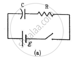
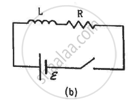
(a) The charge on C just after t = 0 is εC.
(b) The charge on C long after t = 0 is εC.
(c) The current in L just before t = t0 is ε/R.
(d) The current in L long after t = t0 is ε/R.
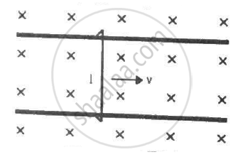
Figure shows a wire sliding on two parallel, conducting rails placed at a separation l. A magnetic field B exists in a direction perpendicular to the plane of the rails. What force is necessary to keep the wire moving at a constant velocity v?
The following diagram shows a fixed coil of several turns connected to a center zero galvanometer G and a magnet NS which can move in the direction shown in the diagram.
- Describe the observation in the galvanometer if
- The magnet is moved rapidly,
- The magnet is kept still after it has moved into the coil
- The magnet is then rapidly pulled out the coil.
- How would the observation in (i) of part (a) change if a more powerful magnet is used?

Fill in the blanks by writing (i) Only soft iron, (ii) Only steel, (iii) Both soft-iron and steel for the material of core and/or magnet.
D.C. motor ______.
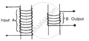
Complete the following diagram of a transformer and name the parts labeled A and B. Name the part you have drawn to complete the diagram . What is the material of this part? In this transformer a step-up or step-down? Why?
Answer the following:
State the principles of the electric motor and electric generator.
Draw a labelled diagram to show how an electromagnet is made.
State the purpose of soft iron core used in making an electromagnet.
What is an electromagnet? What do you know about the simplest form of an electromagnet?
Using Ampere's law, obtain an expression for the magnetic induction near a current-carrying straight infinitely long wire.
Observe the given figure of Fleming’s Right Hand Rule and write the labels of A and B correctly.
Fleming's left hand rule : electric current : : Fleming's right hand rule : _______
A thin semi-circular conducting ring (PQR) of radius r is falling with its plane vertical in a horizontal magnetic field B, as shown in the figure.
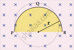
The potential difference developed across the ring when its speed v , is
A square coil of side 30 cm with 500 turns is kept in a uniform magnetic field of 0.4 T. The plane of the coil is inclined at an angle of 30° to the field. Calculate the magnetic flux through the coil.
The magnetic flux passing through a coil perpendicular to its plane is a function of time and is given by OB = (2t3 + 4t2 + 8t + 8) Wb. If the resistance of the coil is 5 Ω, determine the induced current through the coil at a time t = 3 second.
A 50 cm long solenoid has 400 turns per cm. The diameter of the solenoid is 0.04 m. Find the magnetic flux linked with each turn when it carries a current of 1 A.
A layer of atmosphere that reflects medium frequency radio waves which is ineffective during night, is ______.
There is a uniform magnetic field directed perpendicular and into the plane of the paper. An irregular shaped conducting loop is slowly changing into a circular loop in the plane of the paper. Then ______.
A metal plate can be heated by ______.
An expression for oscillating electric field in a plane electromagnetic wave is given as Ez = 300 sin(5π × 103x - 3π × 1011t)Vm-1 Then, the value of magnetic field amplitude will be ______. (Given: speed of light in Vacuum c = 3 × 10⁸ ms-1)
The primary of a transformer has 400 turns while the secondary has 2000 turns. If the power output from the secondary at 1000 Vis 12 kW, what is the primary voltage?
