Advertisements
Advertisements
प्रश्न
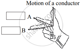
Name the following diagram and explain the concept behind it.
Advertisements
उत्तर
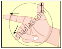
Name: Fleming’s right-hand rule
Concept: It represents Fleming’s right-hand rule used for finding the direction of the induced current with respect to the directions of the magnetic field and motion of the conductor.
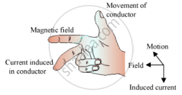
The direction of the current induced in a conductor can be obtained by holding the thumb, the index finger, and the middle finger of your right hand mutually perpendicular to each other. In this situation, the thumb indicates the direction of the motion of the conductor, the index finger points along the magnetic field, and the middle finger points along the current induced in the conductor.
APPEARS IN
संबंधित प्रश्न
State three differences between direct current and alternating current.
Explain different ways to induce current in a coil.
Two circular coils A and B are placed closed to each other. If the current in the coil A is changed, will some current be induced in the coil B? Give reason.
Prove theoretically (electromagnetic induction) `e = (dphi)/(dt)`
If ‘R’ is the radius of dees and ‘B’ be the magnetic field of induction in which positive charges (q) of mass (m) escape from the cyclotron, then its maximum speed (vmax) is _______.
A) `(qR)/(Bm)`
B)`(qm)/(Br)`
C) `(qBR)/m`
D) `m/(qBR)`
A circular coil of cross-sectional area 200 cm2 and 20 turns is rotated about the vertical diameter with angular speed of 50 rad s−1 in a uniform magnetic field of magnitude 3.0 × 10⁻²T. Calculate the maximum value of the current in the coil.
The north-south polarities of an electromagnet can be found easily by using:
(a) Fleming's right-hand rule
(b) Fleming's left-hand rule
(c) Clock face rule
(d) Left-hand thumb rule
State whether the following statement are true or false:
A generator works on the principle of electromagnetic induction.
State whether the following statement are true or false:
A motor works on the principle electric generator?
When current is 'switched on' and 'switched off' in a coil, a current is induced in another coil kept near it. What is this phenomenon known as?
- What kind of energy change takes place when a magnet is moved towards a coil having a galvanometer at its ends?
- Name the phenomenon.
Name and state the law which determines the direction of induced current.
or
State Fleming’s right-hand rule.
A light metal disc on the top of an electromagnet is thrown up as the current is switched on. Why? Give reason.
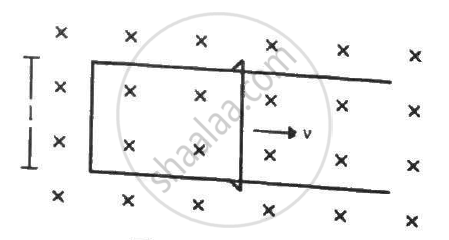
Figure shows a long U-shaped wire of width l placed in a perpendicular magnetic field B. A wire of length l is slid on the U-shaped wire with a constant velocity v towards right. The resistance of all the wires is r per unit length. At t = 0, the sliding wire is close to the left edge of the U-shaped wire. (a) Calculate the force needed to keep the sliding wire moving with a constant velocity v. (b) If the force needed just after t = 0 is F0, find the time at which the force needed will be F0/2.0
Can a transformer work when it is connected to a D.C. source? Give a reason.
Fill in the blanks by writing (i) Only soft iron, (ii) Only steel, (iii) Both soft-iron and steel for the material of core and/or magnet.
A. C. generator______.
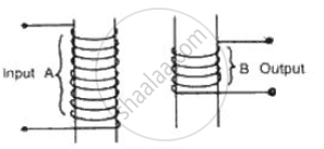
Complete the following diagram of a transformer and name the parts labeled A and B. Name the part you have drawn to complete the diagram . What is the material of this part? In this transformer a step-up or step-down? Why?
State the purpose of soft iron core used in making an electromagnet.
Draw a labelled diagram to make an electromagnet from a soft iron bar. Mark the polarity at its ends in your diagram. What precaution would you observe while making it?
State the condition at which we say the two coils kept close to each other are perfectly coupled with each other.
Observe the given figure of Fleming’s Right Hand Rule and write the labels of A and B correctly.
A thin semi-circular conducting ring (PQR) of radius r is falling with its plane vertical in a horizontal magnetic field B, as shown in the figure.
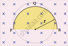
The potential difference developed across the ring when its speed v , is
State Lenz’s law.
Show that Lenz’s law is in accordance with the law of conservation of energy.
The magnetic flux passing through a coil perpendicular to its plane is a function of time and is given by OB = (2t3 + 4t2 + 8t + 8) Wb. If the resistance of the coil is 5 Ω, determine the induced current through the coil at a time t = 3 second.
An induced current of 2.5 mA flows through a single conductor of resistance 100 Ω. Find out the rate at which the magnetic flux is cut by the conductor.
A cylindrical bar magnet (A) and similar unmagnetized cylindrical iron bar (B) are dropped through metallic pipe. The time taken to come down by ____________.
A metal plate can be heated by ______.
For making a strong electromagnet the material of the core should be ______.
A coil of one turn is made of a wire of certain length and then from the same length, a coil of two turns is made. If the same current is passed in both the cases, then the ratio of the magnetic inductions at their centres will be:
A 0.4 m wire, stretched horizontally, carries an electric current of 15 A, in a magnetic field whose magnetic field intensity is 0.1 N/Am. What is the magnitude of the wire?
One solenoid is centered inside another. The outer one has a length of 50.0 cm and contains 6750 coils, while the coaxial inner solenoid is 3.0 cm long and π cm2 in area and contains 150 coils. The current in the outer solenoid is changing at 3000 A/s. The emf induced in the inner solenoid is ______ V.
(Round off to two decimal places.)
The primary of a transformer has 400 turns while the secondary has 2000 turns. If the power output from the secondary at 1000 Vis 12 kW, what is the primary voltage?
