Advertisements
Advertisements
प्रश्न
Give an illustration of determining direction of induced current by using Lenz’s law.
Advertisements
उत्तर
- Move the bar magnet towards the solenoid with north pole pointing solenoid.
- When the Magnetic flux increases in the coil, an induced current is produced, and the coil becomes a magnetic dipole.
- According to Lenz law, induced current opposes the movement of the north pole towards coil.
(a)
(b)
(c)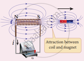
- It is possible if end nearer to magnet becomes the north pole, then it repels the north pole of the magnet and oppose the movement of the magnet.
- The direction of induced current is found by the right-hand thumb rule.
- When a bar magnet is withdrawn, the nearer end becomes south pole which attracts the north pole of the bar magnet, opposing the receding motion of the magnet.
7. Direction of induced current can be found from Lenz law.
APPEARS IN
संबंधित प्रश्न
Name a common device that uses electromagnets.
How does an electromagnet differ forma permanent magnet?
An induced current is produced when a magnet is moved into a coil. The magnitude of induced current does not depend on:
(a) the speed with which the magnet is moved
(b) the number of turns of the coil
(c) the resistivity of the wire of the coil
(d) the strength of the magnet
The coil of a moving-coil galvanometer keeps on oscillating for a long time if it is deflected and released. If the ends of the coil are connected together, the oscillation stops at once. Explain.
Calculate the dimensions of (a) \[\int \overrightarrow{E} . d \overrightarrow{l,}\] (b) vBl and (c) \[\frac{d \Phi_B}{dt}.\] The symbols have their usual meaning.
Fig. shows a simple form of an A.C. generator.
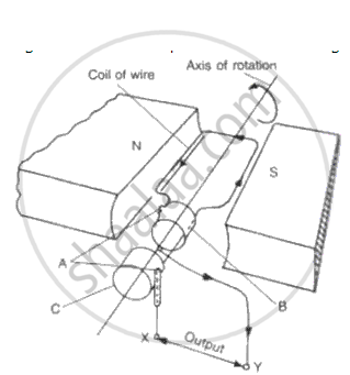
(a) Name the parts labeled A and B.
(b) What would be the effect of doubling the number of turns on the coil if the speed of rotation remains unchanged?
(c) Which of the output terminals is positive if the coil is rotating in the
direction shown in the diagram (anticlockwise)?
( d ) What is the position of the rotating coil when p.d. across its ends is zero? Explain why p.d. is zero when the coil is at this position .
(e) Sketch a graph showing how the p.d. across the ends of the rotating coil varies with time for an A.C. dynamo.
( f) On th e same sheet of paper and vertically below the first graph using the same time scale, sketch graphs to show the effect of
(i) Doubling the speed of rotation and at the same time keeping
the field and the number of turns constant,
(ii ) Doubling the number of turns on the coil and at the same time
doubling the speed of rotation of the coil, keeping th e speed
constant.
Answer the following:
State the principles of the electric motor and electric generator.
Write Fleming’s right hand thumb rule with the help of diagram.
A galvanometer is an instrument that can detect the presence of a current in a circuit.
A conducting bar of length L is free to slide on two parallel conducting rails as shown in the figure

Two resistors R1 and R2 are connected across the ends of the rails. There is a uniform magnetic field `vec"B"` pointing into the page. An external agent pulls the bar to the left at a constant speed v. The correct statement about the directions of induced currents I1 and I2 flowing through R1 and R2 respectively is:
