Topics
Electric Charges and Fields
- Electric Charges
- Properties of Electric Charge
- Simple Atomic Structure
- Conductors and Insulators
- Mechanism of Charging of an Object
- Charging by Friction
- Charging by Conduction
- Charging by Induction
- Coulomb's Law (Scalar Form): Force Between Two Point-Charges
- Coulomb's Law in Vector Form
- Forces Between Multiple Charges: Superposition Principle
- Equilibrium of System of Charges
- Electric Field
- Intensity of Electric Field
- Electric Field Intensity Due to a Point-Charge
- Intensity of Electric Field due to a Continuous Charge Distribution
- Electric Lines of Force
- Electric Dipole
- Electric Field due to an Electric Dipole
- Motion of an Electric Dipole in a Uniform Electric Field
- Effect of a Uniform Electric Field on the Motion of a Charged Particle
- Equilibrium of a Charged Body in a Uniform Electric Field
- Introduction to Gauss' Theorem of Electrostatics
- Area Vector
- Flux of a Vector Field
- Gauss' Theorem
- Gaussian Surface and its Properties
- Applications of Gauss' Theorem > Electric Field due to a Point Charge
- Applications of Gauss' Theorem > Electric Field due to an Infinite Line of Charge
- Applications of Gauss' Theorem > Electric Field due to an Infinite Plane Sheet of Charge
- Applications of Gauss' Theorem > Electric Field due to Two Infinite Parallel Sheets of Charge
- Applications of Gauss' Theorem > Electric Field Intensity Just Outside a Charged Conductor
- Applications of Gauss' Theorem > Electric Field due to a Uniformly Charged Thin Spherical Shell
- Applications of Gauss' Theorem > Electric Field due to a Uniformly Charged Sphere
Electrostatics
Electrostatic Potential, Potential Energy and Capacitance
- Introduction to Electric Potential
- Electric Potential: A Quantitative Approach
- Potential Difference
- Work Done in Moving a Charge in an Electric Field
- Acceleration of a Charged Particle Between Two Points in an Electric Field
- Electric Potential Due to a Point Charge
- Potential due to a Group of Point Charges
- Potential Gradient
- Electric Field as Gradient of Electric Potential: Relation between E and V
- Equipotential Surfaces
- Electric Potential Energy of a System of Charges
- Charged Body Between Parallel Plates
- Potential Due to an Electric Dipole
- Work Done in Rotating an Electric Dipole in an Electric Field
- Electric Potential Energy of an Electric Dipole in an Electrostatic Field
- Electrostatics of Conductors
- Free and Bound Charges
- Dielectrics
- Electric Polarisation of Dielectrics
- Capacitance of a Conductor
- Capacitance of an Isolated Spherical Conductor
- Potential Energy of a Charged Conductor
- Redistribution of Charges: Common Potential
- Introduction to a Capacitor
- The Parallel Plate Capacitor
- Expression for Capacitance of a Parallel-Plate Capacitor
- Dependence of the Capacitance of a Capacitor
- Capacitance of a Parallel-Plate Capacitor with Dielectric Slab between Plates
- Combination of Capacitors
- Energy Stored in a Charged Capacitor
- Force between the Plates of a Charged Parallel-Plate Capacitor
- Effect of Dielectric Insertion on a Capacitor: with and Without a Battery
- Variation of Electric Field and Potential Due to a Charged Sphere
Current Electricity
Magnetic Effects of Current and Magnetism
Electric Resistance and Ohm's Law
- Introduction Tо Current Electricity
- Electric Current
- Current Density
- Electric Resistance
- Ohm's Law
- Experimental Verification of Ohm’s Law and Ohmic Resistors
- Exceptions of Ohm's Law : Non-Linear V-I Characteristics
- Mechanism of Flow of Electrons Through the Metal Conductors
- Mobility of Electrons
- Current, Drift Velocity Relation
- Derivation of Ohm's Law with Current Drift Velocity Relation
- Specific Resistance or Electrical Resistivity
- Ohm's law in Vector Form
- Colour Code of Carbon Resistors
- Combinations of Resistances
- An Important Deduction
- Electric Energy and Power
- Commercial Units of Electricity Consumption
- Introduction: D.C. Circuits and Measurements
- Electric cell
- Electromotive Force of a Cell
- Terminal Potential Difference
- Internal Resistance of a Cell
- Relation between E, V, and r
- Combinations of Cells
- Kirchhoff’s Laws
- Wheatstone Bridge
- Metre Bridge: Slide-Wire Bridge
- Potentiometer
Electromagnetic Induction and Alternating Currents
Moving Charges and Magnetism
- Magnetic Effect of Electric Current
- Oersted's Experiment
- Concept of Magnetic Field
- Force on a Moving Charge in a Uniform Magnetic Field
- Definition of Magnetic Field on the Basis of Magnetic Force
- Motion of Charged Particles in a Uniform Magnetic Field
- Lorentz Force
- Cyclotron
- Force on a Current-Carrying Conductor Placed in a Uniform Magnetic Field
- Magnetic Field Due to a Current-carrying Conductor: Biot-savart's Law
- Comparison of Coulomb's Law and Biot-Savart's Law
- Rules to Determine the Direction of Magnetic Field
- Applications of Biot-Savart's Law > Magnetic Field at the Axis of a Circular Current-carrying Loop
- Applications of Biot-Savart's Law > Magnetic Field Due to a Straight Current-carrying Conductor of Finite Size
- Applications of Biot-Savart's Law > Magnetic Field at the Centre of a Circular Current-carrying Loop
- Ampere’s Circuital Law
- Applications of Ampere’s Circuital Law > Magnetic Field of a Long Straight Thin Wire
- Applications of Ampere’s Circuital Law > Magnetic Field of a Long Straight Solenoid
- Applications of Ampere’s Circuital Law > Magnetic Field of a Toroidal Solenoid
- Force Between Two Parallel Current-Carrying Conductors : Definition of Ampere
- Comparison Between Electric and Magnetic Forces
- Torque on a Current-Loop in a Uniform Magnetic Field
- Atom as a Magnetic Dipole
- Moving Coil Galvanometer
- Sensitivity of a Galvanometer
- Conversion of a Galvanometer in Ammeter
- Conversion of a Galvanometer in Voltmeter
Electromagnetic Waves
Magnetism and Matter
- Concept of Magnetism
- Current Loop as a Magnetic Dipole : Magnetic Dipole Moment of Current Loop
- Magnetic Dipole Moment of a Revolving Electron
- The Bar Magnet
- Magnetic Lines of Force
- Current-carrying Solenoid: An Electromagnetic Equivalent of a Bar-magnet
- Magnetic Field of a Magnetic Dipole (Small Bar Magnet)
- Torque on a Magnetic Dipole (Bar Magnet) in a Uniform Magnetic Field
- Potential Energy of a Magnet in a Magnetic Field
- Earth’s Magnetic Field
- Elements of the Earth's Magnetic Field > Angle of Declination
- Elements of the Earth's Magnetic Field > Angle of Dip or Magnetic Inclination
- Elements of the Earth's Magnetic Field > Horizontal Component of Earth's Magnetic Field
- Classification of Substances According to their Magnetic Behaviour
- Some Important Terms Used in Magnetism
- Properties of Dia, Para, and Ferromagnetic Substances
- Explanation of Dia, Para and Ferromagnetism on the Basis of Atomic Model of Magnetism
- Explanation of Demagnetisation by Atomic Model
- Hysteresis: Retentivity and Coercivity
- Differences in Magnetic Properties of Soft Iron and Steel
- Selection of Magnetic Materials
Optics
Electromagnetic Induction
- Introduction to Electromagnetic Induction
- Magnetic Flux
- Electromagnetic Induction: Experimental Demonstration
- Faraday's Laws of Electromagnetic Induction
- Induced Current and Induced Charge
- Methods of Changing the Magnetic Flux
- Motion of a Straight Conductor in a Uniform Magnetic Field (Motional EMF)
- Motional Emf: A Conceptual Approach Based on Lenz's Law and Dynamic Flux Analysis
- Motional emf in Rotating a Conducting Rod in a Uniform Magnetic Field
- Self – Induction
- Self-Inductance of a Long Solenoid
- Energy Stored in an Inductor
- Some Examples of the Effect of Self-induced Current
- Mutual Inductance
- Mutual Inductance of Two Long Coaxial Solenoids
- Eddy Currents or Foucault Currents
Alternating Current
- Introduction to Ac and Aс Circuits
- Alternating Voltage and Current Developed in a Coil Rotating in Magnetic Field
- Some Definitions Regarding Alternating Voltage and Current
- Mean (or Average) Value of Alternating Current (or Voltage)
- Root-Mean-Square Value of Alternating Current
- Phasors and Phasor Diagrams
- Types of Ac Circuits > Circuit Containing Resistance Only
- Types of Ac Circuits > Circuit Containing Inductance Only
- Types of Ac Circuits > Circuit Containing Capacitance Only
- Types of Ac Circuits > Circuit Containing Inductance and Resistance in Series (L-r Series Circuit)
- Types of Ac Circuits > Circuit Containing Capacitance and Resistance in Series (C-R Series Circuit)
- Types of Ac Circuits > Circuit Containing Inductance and Capacitance (L-C Circuit)
- Types of Ac Circuits > Circuit Containing Inductance, Capacitance and Resistance in Series (L-C-R Series Circuit)
- Power in AC Circuit
- Wattless Current
- Half Power Points, Bandwidth and Q-Factor
- Choke Coil
- Electrical Oscillations in L-C Circuit
- Resonant Circuits
- Frequency Response of AC Circuits
- Alternating-Current Generator
- Transformers
- Utility of Alternating Current in Comparison to Direct Current
Dual Nature of Radiation and Matter
Electromagnetic Waves
- Introduction to Electromagnetic Waves
- Displacement Current
- Relation Between Conduction Current and Displacement Current
- Nature of Electromagnetic Waves
- Field Magnitude Relation in Free Space
- Important Characteristics of Electromagnetic Waves
- Transverse Nature of Electromagnetic Waves (Qualitative Idea)
- Transverse Nature of Electromagnetic Waves (Quantitative Analysis)
- Electromagnetic Spectrum
- Maxwell's Equation
- Energy Density in Electromagnetic Waves
- Overview: Electromagnetic Waves
Atoms and Nuclei
Ray Optics and Optical Instruments
- Ray Optics Or Geometrical Optics
- Spherical Mirrors
- Few Definitions Related to Spherical Mirrors
- Relation Between Focal Length and Radius of Curvature of a Spherical Mirror
- Rules to Trace the Image Formed by Spherical Mirrors
- Conditions of Image Formation
- Position and Nature of Image Formed by Spherical Mirrors
- Sign Convention
- Mirror Formula for Concave Mirror
- Mirror Formula for Convex Mirror
- Linear Magnification by Spherical Mirrors
- Uses of Spherical Mirrors
- Introduction to Refraction at a Plane Interface
- Refraction of Light
- Laws of Refraction
- The Refractive Index
- Cause of Refraction
- Physical Significance of Refractive Index
- Reversibility of Light
- Refraction through Parallel Multiple Media
- Refraction of Light Through a Rectangular Glass Block
- Real and Apparent Depths: Normal Displacement
- Critical Angle
- Total Internal Reflection
- Applications of Total Internal Reflection
- Introduction to Refraction at Curved Surfaces
- Coordinate Geometry Sign Convention for Measuring Distances and Lengths (Refraction)
- Refraction at Concave Spherical Surface
- Refraction at a Convex Spherical Surface
- Concept of Lenses
- Converging and Diverging Actions of Lenses
- Some Definitions Related to Lens
- Lens Maker's Formula
- Factors Affecting Focal Length of a Lens
- Image Formation by Thin Lenses
- Ray Diagrams for Formation of Image by a Convex Lens
- Image Formation by Lenses Made of Multiple Materials
- Ray Diagram for Formation of Image by a Concave Lens
- Linear Magnification by Spherical Lenses
- Power of a Lens
- Combined Focal Length of Two Thin Lenses in Contact
- Combination of Lenses and Mirrors
- Prism
- Refraction of Light through a Prism
- Specific Conditions for Emergent Ray
- Dispersion of White Light by a Prism : Angular Dispersion
- Dispersive Power of an Optical Medium
- The Rainbow
- Scattering of Light-Rayleigh's Law
- Phenomena Based Upon Scattering of Light
- Introduction to Optical Instruments
- Power of Aссоmmodation of the Eye
- Visual Angle : Magnifying Power of Optical Instruments
- Magnifying Power of Microscope and Telescope in Terms of Visual Angle
- Simple Microscopе
- Compound Microscope
- Astronomical Telescope (Refracting Type)
- Reflecting Telescope
- Telescope Vs Compound Microscоре
- Resolving Power of Optical Instruments
- Overview: Reflection of Light: Spherical Mirrors
Electronic Devices
Communication Systems
Wave Optics
- Introduction to Wave Optics
- Wavefront
- Wave Nature of Light and Huygens' Principle
- Huygens Principle
- Behaviour of Plane Wavefront in Reflection and Refraction
- Reflection of a Plane Wave by a Plane Surface
- Refraction of a Plane Wave
- Optical Path
- Effect on Wavelength of Light in Going from One Medium to Another
- Interference of Light
- Principle of Superposition of Waves
- Interference of Light Waves and Young’s Experiment
- Conditions for Constructive and Destructive Interference of Light
- Some Additional Information about Interference
- Expression for Fringe Width in Young's Double-slit Experiment
- Change in Fringe Width Under Various Conditions
- No Interference by Two Independent Light-Sources : Coherent Sources
- Conditions for Sustained Interference of Light Waves
- Effect of Introducing a Thin Transparent Plate in the Path of One of the Interfering Beams
- Diffraction of Light
- Types of Diffraction
- Fraunhofer's Diffraction Due to a Single-slit
- Interference Vs Diffraction
- Overview: Wave Optics
Dual Nature of Radiation and Matter
- Understanding Dual Nature of Radiation and Matter
- Electron Emission
- Photoelectric Effect - Hertz’s Observations
- Hertz and Lenard's Observations
- Laws of Photoelectric Emission
- Planck's Photon Hypothesis: Quantisation of Radiation
- Einstein's Explanation of Photoelectric Effect: Photoelectric Equation
- Determination of Planck's Constant
- Energy and Momentum of Photon
- Particle Nature of Light: The Photon
- Wave Nature of a Particle: De-broglie's Thought
- de-Broglie Wavelength of Matter Waves
- Salient Features of Matter Waves
- de-Broglie Wavelength of Electron
- Experimental Demonstration of de-Broglie (Matter) Waves
- Overview: Dual Nature of Radiation and Matter
Atoms
- Atoms: Windows into Thе Invisible World
- Alpha-particle Scattering and Rutherford’s Nuclear Model of Atom
- Distance of Closest Approach of α-particle to the Nucleus-size of Nucleus
- Atomic Models: Historical Development
- Rutherford’s Atomic Model
- Atomic Spectra
- Bohr’s Model for Hydrogen Atom
- Bohr's Theory of Hydrogen-like Atoms: Radii of Permitted Orbits
- Discrete Energy Levels of Atom
- Explanation of the Line Spectrum and Estimation of Wavelength by Energy Transitions
- Hydrogen Spectrum
- Excitation and Ionisation Energy of Hydrogen Atom
- Uses of Rydberg Constant
- De Broglie’s Explanation of Bohr’s Second Postulate of Quantisation
- Overview: Atom, Origin of Spectra : Bohr's Theory of Hydrogen Atom
Nuclei
- Introduction to the Physics of the Nucleus
- Nuclear Force
- Atomic Masses and Composition of Nucleus
- Nuclear Size, Shape and Density
- Atomic Masses : Unified Atomic Mass Unit
- Isotopes
- Isobars
- Isotones
- Mass - Energy
- Pair-Production and Pair-Annihilation
- Mass Defect and Binding Energy
- Nuclear Reactions
- Q-value (Disintegration Energy) Or Energy of Nuclear Reaction
- Nuclear Energy and Stability: Exothermic Nuclear Reactions
- Nuclear Fission
- Chain Reaction in Nuclear Fission
- Multiplication or Reproduction Factor of a Chain Reaction
- Differences Between Radioactive Decay and Nuclear Fission
- Nuclear Reactor
- Nuclear Fusion
- Nuclear Bomb
- Chain Reaction-Controlled and Uncontrolled; Nuclear Reactor and Nuclear Bomb
- Stellar Energy Or Thermonuclear Energy
- Nuclear Holocaust
- Overview: Nuclei
Semiconductor Electronics
- Concept of Semiconductor Electronics
- Materials-Conductors, Insulators and Semiconductors
- Energy Bands in Materials
- Classification of Metals, Conductors and Semiconductors
- Electrons and Holes in Semiconductors
- Intrinsic Semiconductor
- Extrinsic Semiconductor
- Distinction Between Intrinsic and Extrinsic Semiconductors
- N-type VS P-type Semiconductors
- Electric Current in an Intrinsic Semiconductor
- Electric Conductivity and Resistivity of an Intrinsic Semiconductor
- Formation of P-N Junction
- Flow of Current Across Junction Diode: Forward and Reverse Biasings of Junction
- I-V characteristics in Forward and Reverse Biased P-N Junction Diode
- p-n Junction Diode as a Rectifier
- Special Purpose P-n Junction Diodes
- Overview: Semiconductor Electronics
Junction Diodes
Junction Transistors
Logic Gates
Communication Systems
Introduction
Self-induction is the phenomenon where a changing current in a coil induces an EMF in the same coil, opposing the change that caused it. Think of it as the "electrical inertia" of a circuit — it resists sudden changes in current, just as mechanical inertia resists sudden changes in motion.
Definition: Self-Induction
The phenomenon of electromagnetic induction in which a change in current through a coil induces an EMF in the same coil, opposing the change in current, is called self-induction.
Definition: Coefficient of Self-Inductance
The self-inductance of a coil is defined as the ratio of the total magnetic flux linkage to the current flowing through it.
Formula: Coefficient of Self-Inductance
NΦB = LI
Where:
- N = number of turns
- ΦB = magnetic flux linked per turn
- I = current flowing through the coil
- L = coefficient of self-inductance (self-inductance)
Conceptual Link to Lenz's Law
- When current in a coil increases → flux linked with coil increases → induced EMF opposes the increase (opposes growth of current).
- When current in a coil decreases → flux linked with the coil decreases → induced EMF opposes the decrease (opposes decay of current).
- This opposing behaviour is a direct consequence of Lenz's Law — the induced EMF always opposes the cause producing it.
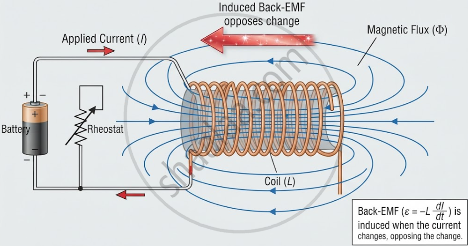
Mathematical Expression
The induced EMF due to self-induction is given by:
- ε = −L\[\frac {ΔI}{Δt}\]
Step-by-Step Derivation
- Flux linkage of coil: NΦB = LI
- By Faraday's Law: ε = −\[\frac {d(NΦ_B)}{dt}\]
- Substituting: ε = −\[\frac {d(LI)}{dt}\]
- Since L is constant for a given coil geometry: ε = −L\[\frac {dI}{dt}\]
Negative sign significance: Indicates that the induced EMF always opposes the change in current (direction, not magnitude).
Unit and Dimensions
| Quantity | Symbol | SI Unit | Conversion |
|---|---|---|---|
| Self-Inductance | L | Henry (H) | 1 H = 10³ mH = 10⁶ µH |
| Millihenry | mH | — | 1 mH = 10⁻³ H |
| Microhenry | µH | — | 1 µH = 10⁻⁶ H |
- 1 Henry: A coil has a self-inductance of 1 henry if a current change of 1 A/s induces an EMF of 1 volt in it.
- Dimensional Formula: [ML2T−2A−2]
Key Properties of Self-Inductance
- Self-inductance depends only on the geometry of the coil (number of turns, area, length, core material) — not on the current or EMF.
- An ideal, infinitely thin straight wire has zero self-inductance because it encloses no appreciable flux.
- An ideal inductor has zero resistance and only opposes change in current, never steady current.
- Inductors do not oppose current itself — they oppose only the rate of change of current.
- Self-inductance is analogous to inertia in mechanics — it represents electrical "resistance to change."
Example
Problem: A coil of 200 turns and self-inductance 20 mH carries a current of 4 mA. Find the magnetic flux linked per turn.
Solution:
Given: N = 200, L = 20 mH = 20 × 10-3 H, I = 4 mA = 4 × 10⁻³ A
Using NΦB = LI:
- ΦB = \[\frac {LI}{N}\] = \[\frac {20×10^{−3}×4×10^{−3}}{200}\]
- ΦB = 4 × 10⁻⁷ Wb
Answer: Flux per turn = 4 × 10⁻⁷ Wb
Real-Life Analogy
Imagine a loaded truck moving at constant speed. To suddenly speed it up or stop it requires extra force because of its inertia. Similarly, an inductor "resists" a sudden change in current — it needs extra EMF (energy) to change the current quickly. This is why self-inductance is often called electrical inertia.
Everyday Applications:
- Chokes/ballasts in tube lights and fluorescent lamps
- Inductors in filter circuits (radios, power supplies)
- Ignition coils in vehicles (sudden current interruption produces high voltage spark)
