Advertisements
Advertisements
Question
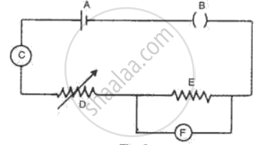
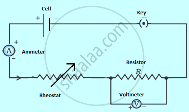
Fig. represents the circuit used for the verification of Ohm's law. Label the parts from A to F. state the function of each.
Advertisements
Solution
Functions:
(A) Cell- It provides the potential difference in the circuit.
(B) Key- It serves as a switch in the circuit. It supplies or cuts off current as required.
(C) Ammeter- It measures the current in the circuit.
(D) Rheostat- It helps to change the resistance of the circuit without changing its voltage.
(E) Resistor- It provides a constant resistance in the circuit.
(F) Voltmeter- It measure the potential drop across the resistor.
APPEARS IN
RELATED QUESTIONS
What will be the change in the current if the potential difference is kept constant and the resistance of the circuit is made four times?
- It will remain unchanged.
- It will become four times.
- It will become one-fourth.
- It will become half.
A resistance of 40 ohms and one of 60 ohms are arranged in series across 220 volt supply. Find the heat in joules produced by this combination of resistances in half a minute.
State Ohm’s law and draw a neat labelled circuit diagram containing a battery, a key, a voltmeter, an ammeter, a rheostat and an unknown resistance to verify it.
Calculate the current flowing through a wire of resistance 5 Ω connected to a battery of potential difference 3 V.
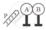
Two metallic spheres A and B kept on insulating stands are in contact with each other. A positively charged rod P is brought near the sphere A as shown in the figure. The two spheres are separated from each other, and the rod P is removed. What will be the nature of charges on spheres A and B?
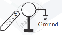
A metal sphere is kept on an insulting stands. A negatively charged rod is brought near it, then the sphere is earthed as shown. On removing the earthing, and taking the negatively charged rod away, what will be the nature of charge on the sphere? Give reason for your answer.
The ratio of the potential difference to the current is known as ________.
State microscopic form of Ohm’s law.
The heat produced by a 100 w heater in 2 minute is equal to
Two conductors are made of the same material and have the same length. Conductor A is a solid wire of diameter 1 mm. Conductor B is a hollow tube of outer diameter 2 mm and inner diameter 1 mm. Find the ratio of resistance RA to RB.
