Advertisements
Advertisements
प्रश्न
Explain the working of P-N junction diode in forward and reverse biased mode.
Advertisements
उत्तर
If a germanium crystal or silicon crystal is doped during manufacture in such a way that half of it is p-type and other half is n-type, we get p-n junction.
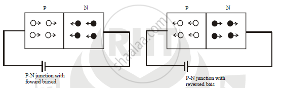
(a) Forward biased: A battery is connected across p-n junction diode such that, p-type is connected to positive terminal and n-type is connected to negative terminal, then it is called forward biased. The potential difference applied should be more than 0.3 V for germanium and more than 0.7 V for silicon. Then holes from p-type region and electrons from n-type region moves towards barrier and it decreases width and height of
barrier. Hence an electric current flows through circuit. When applied potential is zero, then current also equal to zero. When P.D. Increases the current is also increases but very slowly. When applied P.D. is more than potential barrier, current in creases rapidly. This voltage is called knee voltage. The forward biased voltage at which the current through diode increases rapidly is called knee voltage
b) Reversed biased : A battery is connected across p-n junction diode such that, p-type is connected to negative terminal and n-type is connected to positive terminal, then it is called reversed biased. The holes from p type region and electrons from n-type region moves away from junction and it increases width and height of barrier. Hence there is no flow of an electric current in ideal case. In actual case current is very small (inμA) . The width of potential barrier increases and diode offer very high resistance. The very small current flows through circuit is called as reverse current. If reversed bias voltage increased then the kinetic energy of electrons increases. At certain reversed bias voltage the K.E. of electrons increases enough and they knock out the electrons from semiconductor atoms\ Therefore current suddenly increase. That certain reversed bias voltage is called as breakdown voltage. At breakdown voltage the current increases suddenly and destroy the junction permanently. The reversed bas voltage at which P-N junction breaks and current suddenly increases is called as breakdown voltage.
APPEARS IN
संबंधित प्रश्न
With the help of neat labelled circuit diagram explain the working of half wave rectifier using semiconductor diode. Draw the input and output waveforms.
Draw its I – V characteristics of photodiode
In the following diagram, is the junction diode forward biased or reverse biased ?
With reference to semiconductor devices, define a p-type semiconductor and a Zener diode.
The graph shown in the figure represents a plot of current versus voltage for a given semiconductor. Identify the region, if any, over which the semiconductor has a negative resistance.

In a photo diode, the conductive increases when the material is exposed to light. It is found that the conductivity changes only if the wavelength is less than 620 nm. What is the band gap?
(Use Planck constant h = 4.14 × 10⁻¹⁵ eV-s, Boltzmann constant k = 8·62 × 10-5 eV/K.)
In semiconductor physics, what is meant by:
(i) rectifier
(ii) an amplifier
(iii) an oscillator
Answer the following question.
Why photodiodes are required to operate in reverse bias? Explain.
With reference to Semiconductor Physics,
Name the diode that emits spontaneous radiation when forward biased.
Of the diodes shown in the following diagrams, which one is reverse biased?
The drift current in a p-n junction is from the ______.
A – pn junction has a depletion layer of thickness .of the order of
In forward bias width of potential barrier in a p + n junction diode
Avalanche breakdown is due to ______.
Consider an npn transistor with its base-emitter junction forward biased and collector base junction reverse biased. Which of the following statements are true?
- Electrons crossover from emitter to collector.
- Holes move from base to collector.
- Electrons move from emitter to base.
- Electrons from emitter move out of base without going to the collector.
In the circuit shown in figure, when the input voltage of the base resistance is 10 V, Vbe is zero and Vce is also zero. Find the values of Ib, Ic and β.

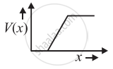
The graph of potential barrier versus width of depletion region for an unbiased diode is shown in graph A. In comparison to A, graphs B and C are obtained after biasing the diode in different ways. Identify the type of biasing in B and C and justify your answer
| ‘A’ | ‘B’ | ‘C’ |
 |
 |
 |
Draw V-I characteristics of a p-n Junction diode.
Explain the formation of the barrier potential in a p-n junction.
Answer the following giving reasons:
A p-n junction diode is damaged by a strong current.
When the p-side and n-side are joined, in which direction do electrons diffuse?
What occurs near the junction when the p-side and n-side are joined?
What is left behind near the junction, creating a depletion layer?
What opposes further diffusion in the depletion layer?
What is the approximate cut-in voltage of a germanium diode?
What is the approximate cut-in voltage of a silicon diode?
Which practical effect is associated with forward bias?
How does effective resistance compare between forward bias after the cut-in voltage and reverse bias before breakdown?
