Advertisements
Advertisements
प्रश्न
Consider a box with three terminals on top of it as shown in figure (a):
 (a) |
Three components namely, two germanium diodes and one resistor are connected across these three terminals in some arrangement. A student performs an experiment in which any two of these three terminals are connected in the circuit shown in figure (b).
 (b) |
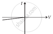
The student obtains graphs of current-voltage characteristics for unknown combination of components between the two terminals connected in the circuit. The graphs are
(i) when A is positive and B is negative
 (c) |
(ii) when A is negative and B is positive
 (d) |
(iii) When B is negative and C is positive
|
(e) |

(iv) When B is positive and C is negative
 (f) |
(v) When A is positive and C is negative
 (g) |
(vi) When A is negative and C is positive
 (h) |
From these graphs of current-voltage characteristics shown in figure (c) to (h), determine the arrangement of components between A, B and C.
Advertisements
उत्तर
The V-I characteristics of these graphs are discussed in points:
(a) In the V-I graph of condition (i), reverse characteristics are shown in figure (c). Here A is connected to the n-side of p-n junction I and B is connected top-side of the p-n junction I with a resistance in series.
(b) In the V-I graph of condition (ii), a forward characteristic is shown in figure (d), where 0.7 V is the knee voltage of p-n junction I. 1/slope = (1/1000) Ω.
It means A is connected to the n-side of p-n junction I and B is connected to the p-side of p-n junction I and resistance R is in a series of p-n junction I between A and B.
(c) In the V-I graph of condition (iii), a forward characteristic is shown in figure (e), where 0.7 V is the knee voltage. In this case, p-side of p-n junction II is connected to C and the n-side of p-n junction II to B.
(d) In V-I graphs of conditions (iv), (v), (vi) also concludes the above connection of p-n junctions I and II along with a resistance R.
Thus, the arrangement of p-n I, p-n II and resistance R between A, B and C will be as shown in the figure.

APPEARS IN
संबंधित प्रश्न
What causes the setting up of high electric field even for small reverse bias voltage across the diode?
When a forward bias is applied to a p-n junction, it ______.
In the following diagram, is the junction diode forward biased or reverse biased ?
What is the use of Zener diode?
Draw a labelled diagram of a full wave rectifier. Show how output voltage varies with time if the input voltage is a sinusoidal voltage.
Why is a zener diode considered as a special purpose semiconductor diode?
With reference to semi-conductors answer the following :
(i) What is the change in the resistance of the semi-conductor with increase in temperature ?
(ii) Name the majority charge carriers in n-type semi-conductor.
(iii) What is meant by doping ?
With reference to a semiconductor diode, what is meant by:
(i) Forward bias
(ii) Reverse bias
(iii) Depletion region
Answer the following question.
Why photodiodes are required to operate in reverse bias? Explain.
Basic materials used in the present solid state electronic devices like diode, transistor, ICs, etc are ______.
What are the applications of p - n Junction diode?
In forward bias width of potential barrier in a p + n junction diode
In the circuit shown in figure, if the diode forward voltage drop is 0.3 V, the voltage difference between A and B is ______.

Can the potential barrier across a p-n junction be measured by simply connecting a voltmeter across the junction?
Draw V-I characteristics of a p-n Junction diode.
Write the property of a junction diode which makes it suitable for rectification of ac voltages.
Describe the following term briefly:
Breakdown voltage in reverse biasing
What is meant by forward biasing of a semiconductor diode?
An ideal PN junction diode offers ______.
