Advertisements
Advertisements
प्रश्न
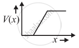
In Figure, Vo is the potential barrier across a p-n junction, when no battery is connected across the junction ______.

पर्याय
1 and 3 both correspond to forward bias of junction.
3 corresponds to forward bias of junction and 1 corresponds to reverse bias of junction.
1 corresponds to forward bias and 3 corresponds to reverse bias of junction.
3 and 1 both correspond to reverse bias of junction.
Advertisements
उत्तर
In Figure, Vo is the potential barrier across a p-n junction, when no battery is connected across the junction 3 corresponds to forward bias of junction and 1 corresponds to reverse bias of junction.
Explanation:
P-N Junction Diode: When a P-type semiconductor is suitably joined to an N-type semiconductor, then the resulting arrangement is called a P-N junction or P-N junction diode.

(1) Depletion region: On account of the difference in concentration of charge carrier in the two sections of the P-N junction, the electrons from N-region diffuse through the junction into P-region and the hole from the P region diffuses into N-region.
Due to diffusion, the neutrality of both N and P-type semiconductor is disturbed and a layer of negatively charged ions appear near the junction in the P-crystal and a layer of positive ions appears near the junction in N-crystal. This layer is called the depletion layer.

- The thickness of the depletion layer is 1 micron = 10–6 m.
- Width of the depletion layer ∝ `1/"Dopping"`
- Depletion is directly proportional to temperature.
- The P-N junction diode is equivalent to the capacitor in which the depletion layer acts as a dielectric.
(2) Potential barrier: The potential difference created across the P-N junction due to the diffusion of electrons and holes is called the potential barrier.
For Ge, VB = 0.3 V and for silicon VB = 0. 7 V
On average the potential barrier in a P-N junction is – 0.5 V and the width of the depletion region = 10–6m.
So the barrier electric field `E = V/d = 0.5/10^-6 = 5 xx 10^5` V/m
The height of the potential barrier is decreased when the p-n junction is forward biased, it opposes the potential barrier junction when the p-n junction is reverse biased and it supports the potential barrier junction, resulting increase in the potential barrier across the junction.
APPEARS IN
संबंधित प्रश्न
Explain the working of P-N junction diode in forward and reverse biased mode.
In the following diagram, is the junction diode forward biased or reverse biased ?
With reference to semi-conductors answer the following :
(i) What is the change in the resistance of the semi-conductor with increase in temperature ?
(ii) Name the majority charge carriers in n-type semi-conductor.
(iii) What is meant by doping ?
A plate current of 10 mA is obtained when 60 volts are applied across a diode tube. Assuming the Langmuir-Child relation \[i_p \infty V_p^{3/2}\] to hold, find the dynamic resistance rp in this operating condition.
The plate current in a diode is 20 mA when the plate voltage is 50 V or 60 V. What will be the current if the plate voltage is 70 V?
The power delivered in the plate circular of a diode is 1.0 W when the plate voltage is 36 V. Find the power delivered if the plate voltage is increased to 49 V. Assume Langmuir-Child equation to hold.
With reference to a semiconductor diode, what is meant by:
(i) Forward bias
(ii) Reverse bias
(iii) Depletion region
Answer the following question.
Why photodiodes are required to operate in reverse bias? Explain.
In forward bias width of potential barrier in a p + n junction diode
Avalanche breakdown is due to ______.
Consider an npn transistor with its base-emitter junction forward biased and collector base junction reverse biased. Which of the following statements are true?
- Electrons crossover from emitter to collector.
- Holes move from base to collector.
- Electrons move from emitter to base.
- Electrons from emitter move out of base without going to the collector.
In the circuit shown in figure, when the input voltage of the base resistance is 10 V, Vbe is zero and Vce is also zero. Find the values of Ib, Ic and β.

The graph of potential barrier versus width of depletion region for an unbiased diode is shown in graph A. In comparison to A, graphs B and C are obtained after biasing the diode in different ways. Identify the type of biasing in B and C and justify your answer
| ‘A’ | ‘B’ | ‘C’ |
 |
 |
 |
Draw V-I characteristics of a p-n Junction diode.
When the p-side and n-side are joined, in which direction do holes diffuse?
What opposes further diffusion in the depletion layer?
How does effective resistance compare between forward bias after the cut-in voltage and reverse bias before breakdown?
Which voltage corresponds to a forward current of \[10\,\mathrm{mA}\]?
What does the comparison of \[10\,\Omega\] in forward bias and \[1.0\times10^{7}\,\Omega\] in reverse bias show?
