Advertisements
Advertisements
Question
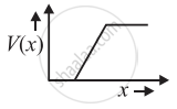
In Figure, Vo is the potential barrier across a p-n junction, when no battery is connected across the junction ______.

Options
1 and 3 both correspond to forward bias of junction.
3 corresponds to forward bias of junction and 1 corresponds to reverse bias of junction.
1 corresponds to forward bias and 3 corresponds to reverse bias of junction.
3 and 1 both correspond to reverse bias of junction.
Advertisements
Solution
In Figure, Vo is the potential barrier across a p-n junction, when no battery is connected across the junction 3 corresponds to forward bias of junction and 1 corresponds to reverse bias of junction.
Explanation:
P-N Junction Diode: When a P-type semiconductor is suitably joined to an N-type semiconductor, then the resulting arrangement is called a P-N junction or P-N junction diode.

(1) Depletion region: On account of the difference in concentration of charge carrier in the two sections of the P-N junction, the electrons from N-region diffuse through the junction into P-region and the hole from the P region diffuses into N-region.
Due to diffusion, the neutrality of both N and P-type semiconductor is disturbed and a layer of negatively charged ions appear near the junction in the P-crystal and a layer of positive ions appears near the junction in N-crystal. This layer is called the depletion layer.

- The thickness of the depletion layer is 1 micron = 10–6 m.
- Width of the depletion layer ∝ `1/"Dopping"`
- Depletion is directly proportional to temperature.
- The P-N junction diode is equivalent to the capacitor in which the depletion layer acts as a dielectric.
(2) Potential barrier: The potential difference created across the P-N junction due to the diffusion of electrons and holes is called the potential barrier.
For Ge, VB = 0.3 V and for silicon VB = 0. 7 V
On average the potential barrier in a P-N junction is – 0.5 V and the width of the depletion region = 10–6m.
So the barrier electric field `E = V/d = 0.5/10^-6 = 5 xx 10^5` V/m
The height of the potential barrier is decreased when the p-n junction is forward biased, it opposes the potential barrier junction when the p-n junction is reverse biased and it supports the potential barrier junction, resulting increase in the potential barrier across the junction.
APPEARS IN
RELATED QUESTIONS
With the help of neat labelled circuit diagram explain the working of half wave rectifier using semiconductor diode. Draw the input and output waveforms.
In a photo diode, the conductive increases when the material is exposed to light. It is found that the conductivity changes only if the wavelength is less than 620 nm. What is the band gap?
(Use Planck constant h = 4.14 × 10⁻¹⁵ eV-s, Boltzmann constant k = 8·62 × 10-5 eV/K.)
The plate current in a diode is 20 mA when the plate voltage is 50 V or 60 V. What will be the current if the plate voltage is 70 V?
The power delivered in the plate circular of a diode is 1.0 W when the plate voltage is 36 V. Find the power delivered if the plate voltage is increased to 49 V. Assume Langmuir-Child equation to hold.
Answer the following question.
Why photodiodes are required to operate in reverse bias? Explain.
Basic materials used in the present solid state electronic devices like diode, transistor, ICs, etc are ______.
We use alloys for making standard resistors because they have ____________.
Of the diodes shown in the following diagrams, which one is reverse biased?
The drift current in a p-n junction is from the ______.
On increasing the reverse biases voltage to a large value in a P – N junction diode-current
When an electric field is applied across a semiconductor ______.
- electrons move from lower energy level to higher energy level in the conduction band.
- electrons move from higher energy level to lower energy level in the conduction band.
- holes in the valence band move from higher energy level to lower energy level.
- holes in the valence band move from lower energy level to higher energy level.
 (a) |
 (b) |
- Name the type of a diode whose characteristics are shown in figure (A) and figure (B).
- What does the point P in figure (A) represent?
- What does the points P and Q in figure (B) represent?
The graph of potential barrier versus width of depletion region for an unbiased diode is shown in graph A. In comparison to A, graphs B and C are obtained after biasing the diode in different ways. Identify the type of biasing in B and C and justify your answer
| ‘A’ | ‘B’ | ‘C’ |
 |
 |
 |
Write the property of a junction diode which makes it suitable for rectification of ac voltages.
Explain the formation of the barrier potential in a p-n junction.
Answer the following giving reasons:
A p-n junction diode is damaged by a strong current.
Draw the circuit arrangement for studying V-I characteristics of a p-n junction diode in (i) forward biasing and (ii) reverse biasing. Draw the typical V-I characteristics of a silicon diode.
Describe the following term briefly:
Minority carrier injection in forward biasing.
With reference to a semiconductor diode, define the depletion region.
What is meant by forward biasing of a semiconductor diode?
