Advertisements
Advertisements
Question
Figure shows the transfer characteristics of a base biased CE transistor. Which of the following statements are true?

At Vi = 0.4 V, transistor is in active state.
At Vi = 1 V, it can be used as an amplifier.
At Vi = 0.5 V, it can be used as a switch turned off.
At Vi = 2.5 V, it can be used as a switch turned on.
Options
a and c
a, c and d
b and c
b, c and d
Advertisements
Solution
b, c and d
Explanation:
According to the above graph transfer characteristics of a base biased common emitter transistor, we note that.
- When Vi= 0.4 V, the output voltage remain same and there is no collection current. So, the transistor circuit is not in an active state.
- When Vi = 1 V (This is in between 0.6 V to 2 V), the transistor circuit is in an active state and when input is increasing output is decreasing because when CE is used as an amplifier input and output voltages are 180° out of phase. Then it is used as an amplifier.
- When Vi = 0.5 V, there is no collector current. The transistor is in a cut-off state. The transistor circuit can be used as a switch to be turned off.
- When Vi = 2.5 V, the collector current becomes maximum and the transistor is in a saturation state and can be used as a switch turned on state.
APPEARS IN
RELATED QUESTIONS
Draw its I – V characteristics of photodiode
In the following diagram, is the junction diode forward biased or reverse biased ?
Why is a zener diode considered as a special purpose semiconductor diode?
In a photo diode, the conductive increases when the material is exposed to light. It is found that the conductivity changes only if the wavelength is less than 620 nm. What is the band gap?
(Use Planck constant h = 4.14 × 10⁻¹⁵ eV-s, Boltzmann constant k = 8·62 × 10-5 eV/K.)
A plate current of 10 mA is obtained when 60 volts are applied across a diode tube. Assuming the Langmuir-Child relation \[i_p \infty V_p^{3/2}\] to hold, find the dynamic resistance rp in this operating condition.
The power delivered in the plate circular of a diode is 1.0 W when the plate voltage is 36 V. Find the power delivered if the plate voltage is increased to 49 V. Assume Langmuir-Child equation to hold.
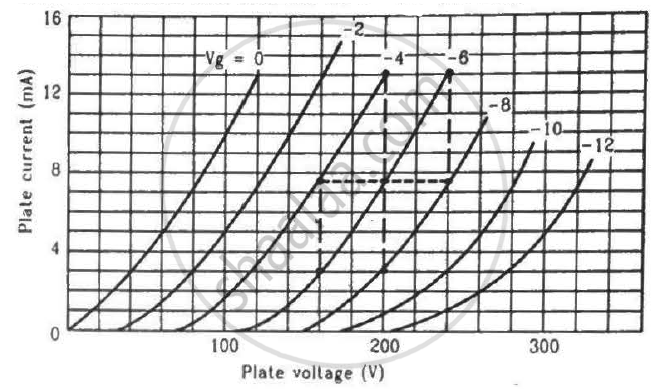
Find the values of rp, µ and gm of a triode operating at plate voltage 200 V and grid voltage −6. The plate characteristics are shown in the figure.
The gain factor of an amplifier in increased from 10 to 12 as the load resistance is changed from 4 kΩ to 8 kΩ. Calculate (a) the amplification factor and (b) the plate resistance.
We use alloys for making standard resistors because they have ____________.
The drift current in a p-n junction is from the ______.
When we apply reverse biased to a junction diode, it
The nature of binding for a crystal with alternate and evenly spaced positive and negatively ions is
Use a transistor as an amplition
The expected energy of the electron at absolute zero is called:-
Avalanche breakdown is due to ______.
 (a) |
 (b) |
- Name the type of a diode whose characteristics are shown in figure (A) and figure (B).
- What does the point P in figure (A) represent?
- What does the points P and Q in figure (B) represent?
In the circuit shown in figure, when the input voltage of the base resistance is 10 V, Vbe is zero and Vce is also zero. Find the values of Ib, Ic and β.

With reference to a semiconductor diode, define the depletion region.
With reference to a semiconductor diode, define the potential barrier.
