Advertisements
Advertisements
प्रश्न
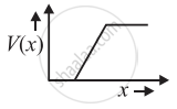
Figure shows the transfer characteristics of a base biased CE transistor. Which of the following statements are true?

At Vi = 0.4 V, transistor is in active state.
At Vi = 1 V, it can be used as an amplifier.
At Vi = 0.5 V, it can be used as a switch turned off.
At Vi = 2.5 V, it can be used as a switch turned on.
पर्याय
a and c
a, c and d
b and c
b, c and d
Advertisements
उत्तर
b, c and d
Explanation:
According to the above graph transfer characteristics of a base biased common emitter transistor, we note that.
- When Vi= 0.4 V, the output voltage remain same and there is no collection current. So, the transistor circuit is not in an active state.
- When Vi = 1 V (This is in between 0.6 V to 2 V), the transistor circuit is in an active state and when input is increasing output is decreasing because when CE is used as an amplifier input and output voltages are 180° out of phase. Then it is used as an amplifier.
- When Vi = 0.5 V, there is no collector current. The transistor is in a cut-off state. The transistor circuit can be used as a switch to be turned off.
- When Vi = 2.5 V, the collector current becomes maximum and the transistor is in a saturation state and can be used as a switch turned on state.
APPEARS IN
संबंधित प्रश्न
What causes the setting up of high electric field even for small reverse bias voltage across the diode?
Plot a graph showing variation of current versus voltage for the material GaAs ?
Why is a zener diode considered as a special purpose semiconductor diode?
In a photo diode, the conductive increases when the material is exposed to light. It is found that the conductivity changes only if the wavelength is less than 620 nm. What is the band gap?
(Use Planck constant h = 4.14 × 10⁻¹⁵ eV-s, Boltzmann constant k = 8·62 × 10-5 eV/K.)
With reference to semi-conductors answer the following :
(i) What is the change in the resistance of the semi-conductor with increase in temperature ?
(ii) Name the majority charge carriers in n-type semi-conductor.
(iii) What is meant by doping ?
A plate current of 10 mA is obtained when 60 volts are applied across a diode tube. Assuming the Langmuir-Child relation \[i_p \infty V_p^{3/2}\] to hold, find the dynamic resistance rp in this operating condition.
The power delivered in the plate circular of a diode is 1.0 W when the plate voltage is 36 V. Find the power delivered if the plate voltage is increased to 49 V. Assume Langmuir-Child equation to hold.
A triode value operates at Vp = 225 V and Vg = −0.5 V.
The plate current remains unchanged if the plate voltage is increased to 250 V and the grid voltage is decreased to −2.5 V. Calculate the amplification factor.
With reference to a semiconductor diode, what is meant by:
(i) Forward bias
(ii) Reverse bias
(iii) Depletion region
In semiconductor physics, what is meant by:
(i) rectifier
(ii) an amplifier
(iii) an oscillator
With reference to Semiconductor Physics,
Name the diode that emits spontaneous radiation when forward biased.
Of the diodes shown in the following diagrams, which one is reverse biased?
Use a transistor as an amplition
In a semiconductor diode, the barrier potential offers opposition to only
In Figure, Vo is the potential barrier across a p-n junction, when no battery is connected across the junction ______.

The breakdown in a reverse biased p–n junction diode is more likely to occur due to ______.
- large velocity of the minority charge carriers if the doping concentration is small.
- large velocity of the minority charge carriers if the doping concentration is large.
- strong electric field in a depletion region if the doping concentration is small.
- strong electric field in the depletion region if the doping concentration is large.
 (a) |
 (b) |
- Name the type of a diode whose characteristics are shown in figure (A) and figure (B).
- What does the point P in figure (A) represent?
- What does the points P and Q in figure (B) represent?
The graph of potential barrier versus width of depletion region for an unbiased diode is shown in graph A. In comparison to A, graphs B and C are obtained after biasing the diode in different ways. Identify the type of biasing in B and C and justify your answer
| ‘A’ | ‘B’ | ‘C’ |
 |
 |
 |
A semiconductor device is connected in series with a battery, an ammeter and a resistor. A current flows in the circuit. If. the polarity of the battery is reversed, the current in the circuit almost becomes zero. The device is a/an ______.
