Advertisements
Advertisements
Question
Consider an npn transistor with its base-emitter junction forward biased and collector base junction reverse biased. Which of the following statements are true?
- Electrons crossover from emitter to collector.
- Holes move from base to collector.
- Electrons move from emitter to base.
- Electrons from emitter move out of base without going to the collector.
Options
d and a
a and b
b and c
a and c
Advertisements
Solution
a and c
Explanation:
Transistor: A junction transistor is formed by sandwiching 2 thin layer of P-type semiconductors between two N-type semiconductors. or by sandwiching a thin taver of V-type semiconductors between two P-type semiconductors.
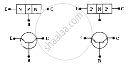
E — Emitter (emits majority charge carriers)
C — Collects majority charge carriers
B — Base (provide proper interaction between E and C)

In normal operation base-emitter is forward biased, i.e., the positive pole of the emitter-base battery is connected to the base and its negative pole is connected to the emitter. And collector-base junction is reverse biased, i.e., the positive pole of the collector base battery is connected to the collector and the negative pole to base. Thus, electron moves from emitter to base and crossovers from emitter to collector.
APPEARS IN
RELATED QUESTIONS
When a forward bias is applied to a p-n junction, it ______.
In a photo diode, the conductive increases when the material is exposed to light. It is found that the conductivity changes only if the wavelength is less than 620 nm. What is the band gap?
(Use Planck constant h = 4.14 × 10⁻¹⁵ eV-s, Boltzmann constant k = 8·62 × 10-5 eV/K.)
We use alloys for making standard resistors because they have ____________.
Of the diodes shown in the following diagrams, which one is reverse biased?
The drift current in a p-n junction is from the ______.
Depletion layer in p - n junction diode consists of
In the circuit shown in figure, if the diode forward voltage drop is 0.3 V, the voltage difference between A and B is ______.

When an electric field is applied across a semiconductor ______.
- electrons move from lower energy level to higher energy level in the conduction band.
- electrons move from higher energy level to lower energy level in the conduction band.
- holes in the valence band move from higher energy level to lower energy level.
- holes in the valence band move from lower energy level to higher energy level.
Can the potential barrier across a p-n junction be measured by simply connecting a voltmeter across the junction?
 (a) |
 (b) |
- Name the type of a diode whose characteristics are shown in figure (A) and figure (B).
- What does the point P in figure (A) represent?
- What does the points P and Q in figure (B) represent?
Draw the circuit arrangement for studying V-I characteristics of a p-n junction diode in (i) forward biasing and (ii) reverse biasing. Draw the typical V-I characteristics of a silicon diode.
Draw a labelled characteristic curve (l-V graph) for a semiconductor diode during forward bias.
Choose the correct circuit which can achieve the bridge balance.
Which battery connection puts a diode in forward bias?
Which practical effect is associated with forward bias?
What is the V-I characteristic curve of a diode?
What current flows in the reverse-bias V-I characteristic before breakdown?
