Advertisements
Advertisements
Question
In a photo diode, the conductive increases when the material is exposed to light. It is found that the conductivity changes only if the wavelength is less than 620 nm. What is the band gap?
(Use Planck constant h = 4.14 × 10⁻¹⁵ eV-s, Boltzmann constant k = 8·62 × 10-5 eV/K.)
Advertisements
Solution
Conductivity of any material increases when the number of free charge carriers in the material increases. When a photo diode is exposed to light, additional electron hole pairs are created in the diode; thus, its conductivity increases. So to change the conductivity of a photo diode, the minimum energy of the incident radiation should be equal to the band gap of the material.
In other words,
Band gap = Energy of the incident radiation
\[\Rightarrow E = \frac{hc}{\lambda}\]
\[ \Rightarrow E = \frac{1242 \text{ eV - nm}}{620 \text{ nm }} = 2.0eV\]
APPEARS IN
RELATED QUESTIONS
What happens when a forward bias is applied to a p-n junction?
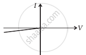
Plot a graph showing variation of current versus voltage for the material GaAs ?
With reference to semi-conductors answer the following :
(i) What is the change in the resistance of the semi-conductor with increase in temperature ?
(ii) Name the majority charge carriers in n-type semi-conductor.
(iii) What is meant by doping ?
The power delivered in the plate circular of a diode is 1.0 W when the plate voltage is 36 V. Find the power delivered if the plate voltage is increased to 49 V. Assume Langmuir-Child equation to hold.
A – pn junction has a depletion layer of thickness .of the order of
Avalanche breakdown is due to ______.
In Figure, Vo is the potential barrier across a p-n junction, when no battery is connected across the junction ______.

In the circuit shown in figure, if the diode forward voltage drop is 0.3 V, the voltage difference between A and B is ______.

Figure shows the transfer characteristics of a base biased CE transistor. Which of the following statements are true?

At Vi = 0.4 V, transistor is in active state.
At Vi = 1 V, it can be used as an amplifier.
At Vi = 0.5 V, it can be used as a switch turned off.
At Vi = 2.5 V, it can be used as a switch turned on.
In the circuit shown in figure, when the input voltage of the base resistance is 10 V, Vbe is zero and Vce is also zero. Find the values of Ib, Ic and β.

Consider a box with three terminals on top of it as shown in figure (a):
 (a) |
Three components namely, two germanium diodes and one resistor are connected across these three terminals in some arrangement. A student performs an experiment in which any two of these three terminals are connected in the circuit shown in figure (b).
 (b) |
The student obtains graphs of current-voltage characteristics for unknown combination of components between the two terminals connected in the circuit. The graphs are
(i) when A is positive and B is negative
 (c) |
(ii) when A is negative and B is positive
 (d) |
(iii) When B is negative and C is positive
|
(e) |

(iv) When B is positive and C is negative
 (f) |
(v) When A is positive and C is negative
 (g) |
(vi) When A is negative and C is positive
 (h) |
From these graphs of current-voltage characteristics shown in figure (c) to (h), determine the arrangement of components between A, B and C.
Write the property of a junction diode which makes it suitable for rectification of ac voltages.
With reference to a semiconductor diode, define the depletion region.
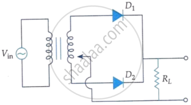
A full wave rectifier circuit diodes (D1) and (D2) is shown in the figure. If input supply voltage Vin = 220 sin (100 πt) volt, then at t = 15 ms.
When the p-side and n-side are joined, in which direction do electrons diffuse?
What opposes further diffusion in the depletion layer?
What is the approximate cut-in voltage of a germanium diode?
Which practical effect is associated with reverse bias before breakdown?
