Advertisements
Advertisements
प्रश्न
In a photo diode, the conductive increases when the material is exposed to light. It is found that the conductivity changes only if the wavelength is less than 620 nm. What is the band gap?
(Use Planck constant h = 4.14 × 10⁻¹⁵ eV-s, Boltzmann constant k = 8·62 × 10-5 eV/K.)
Advertisements
उत्तर
Conductivity of any material increases when the number of free charge carriers in the material increases. When a photo diode is exposed to light, additional electron hole pairs are created in the diode; thus, its conductivity increases. So to change the conductivity of a photo diode, the minimum energy of the incident radiation should be equal to the band gap of the material.
In other words,
Band gap = Energy of the incident radiation
\[\Rightarrow E = \frac{hc}{\lambda}\]
\[ \Rightarrow E = \frac{1242 \text{ eV - nm}}{620 \text{ nm }} = 2.0eV\]
APPEARS IN
संबंधित प्रश्न
Draw a labelled diagram of a full wave rectifier. Show how output voltage varies with time if the input voltage is a sinusoidal voltage.
Plot a graph showing variation of current versus voltage for the material GaAs ?
Find the values of rp, µ and gm of a triode operating at plate voltage 200 V and grid voltage −6. The plate characteristics are shown in the figure.
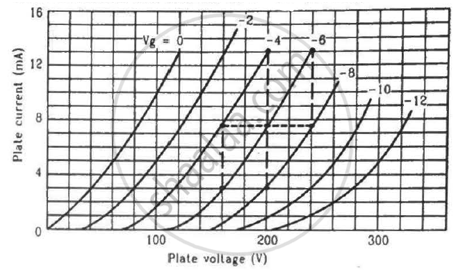
The gain factor of an amplifier in increased from 10 to 12 as the load resistance is changed from 4 kΩ to 8 kΩ. Calculate (a) the amplification factor and (b) the plate resistance.
Basic materials used in the present solid state electronic devices like diode, transistor, ICs, etc are ______.
Diffusion in a p-n junction is due to ______.
What are the applications of p - n Junction diode?
Depletion layer in p - n junction diode consists of
In forward bias width of potential barrier in a p + n junction diode
In Figure, Vo is the potential barrier across a p-n junction, when no battery is connected across the junction ______.

Consider an npn transistor with its base-emitter junction forward biased and collector base junction reverse biased. Which of the following statements are true?
- Electrons crossover from emitter to collector.
- Holes move from base to collector.
- Electrons move from emitter to base.
- Electrons from emitter move out of base without going to the collector.
The breakdown in a reverse biased p–n junction diode is more likely to occur due to ______.
- large velocity of the minority charge carriers if the doping concentration is small.
- large velocity of the minority charge carriers if the doping concentration is large.
- strong electric field in a depletion region if the doping concentration is small.
- strong electric field in the depletion region if the doping concentration is large.
 (a) |
 (b) |
- Name the type of a diode whose characteristics are shown in figure (A) and figure (B).
- What does the point P in figure (A) represent?
- What does the points P and Q in figure (B) represent?
If each diode in figure has a forward bias resistance of 25 Ω and infinite resistance in reverse bias, what will be the values of the current I1, I2, I3 and I4?

Differentiate between the threshold voltage and the breakdown voltage for a diode.
Choose the correct circuit which can achieve the bridge balance.
What opposes further diffusion in the depletion layer?
What is the approximate cut-in voltage of a germanium diode?
What happens to reverse current at the breakdown voltage?
