Advertisements
Advertisements
प्रश्न
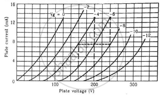
Find the values of rp, µ and gm of a triode operating at plate voltage 200 V and grid voltage −6. The plate characteristics are shown in the figure.
Advertisements
उत्तर
Dynamic plate resistance, `r_p=((deltaV_p)/(deltaI_p)),` at constant grid voltage
We need to find the slope of the graph for a particular value of grid voltage, i.e. Vg = −6 V.
Consider two points for the plot of Vg = −6 V:-
\[r_p = \frac{(240 - 160) V}{(13 - 3) \times {10}^{- 3} A}\]
\[ r_p = \frac{80}{10} \times {10}^3 \Omega\]
\[ r_p = 8 K\Omega\]
\[ g_m = \left( \frac{\delta I_p}{\delta V_g} \right)_{V_P = \text{constant } (200 V)}\]
Consider two points on the 200 V line:-
\[g_m = \frac{(13 - 3) \times {10}^{- 3}}{[( - 4) - ( - 8)]}A\]
\[ g_m = \frac{10 \times {10}^{- 3}}{4}=2.5\text{ mili mho}\]
Amplification factor,
\[\mu = - \left( \frac{∆ V_P}{∆ V_G} \right)_{i_P =\text{ constant}}\]
\[\mu = - \frac{100 - 180}{- 6 - ( - 10)}\]
\[\mu = \frac{80}{4} = 20\]
APPEARS IN
संबंधित प्रश्न
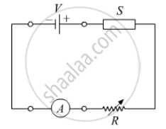
In the following diagram 'S' is a semiconductor. Would you increase or decrease the value of R to keep the reading of the ammeter A constant when S is heated? Give reason for your answer.
What is the use of Zener diode?
Draw a labelled diagram of a full wave rectifier. Show how output voltage varies with time if the input voltage is a sinusoidal voltage.
Plot a graph showing variation of current versus voltage for the material GaAs ?
The power delivered in the plate circular of a diode is 1.0 W when the plate voltage is 36 V. Find the power delivered if the plate voltage is increased to 49 V. Assume Langmuir-Child equation to hold.
With reference to a semiconductor diode, what is meant by:
(i) Forward bias
(ii) Reverse bias
(iii) Depletion region
In semiconductor physics, what is meant by:
(i) rectifier
(ii) an amplifier
(iii) an oscillator
Diffusion in a p-n junction is due to ______.
When we apply reverse biased to a junction diode, it
In forward bias width of potential barrier in a p + n junction diode
On increasing the reverse biases voltage to a large value in a P – N junction diode-current
The breakdown in a reverse biased p–n junction diode is more likely to occur due to ______.
- large velocity of the minority charge carriers if the doping concentration is small.
- large velocity of the minority charge carriers if the doping concentration is large.
- strong electric field in a depletion region if the doping concentration is small.
- strong electric field in the depletion region if the doping concentration is large.
 (a) |
 (b) |
- Name the type of a diode whose characteristics are shown in figure (A) and figure (B).
- What does the point P in figure (A) represent?
- What does the points P and Q in figure (B) represent?
In the circuit shown in figure, when the input voltage of the base resistance is 10 V, Vbe is zero and Vce is also zero. Find the values of Ib, Ic and β.

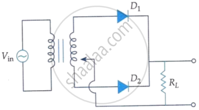
A full wave rectifier circuit diodes (D1) and (D2) is shown in the figure. If input supply voltage Vin = 220 sin (100 πt) volt, then at t = 15 ms.
Choose the correct circuit which can achieve the bridge balance.
When the p-side and n-side are joined, in which direction do electrons diffuse?
Which battery connection puts a diode in forward bias?
Which voltage corresponds to a forward current of \[10\,\mathrm{mA}\]?
