Advertisements
Advertisements
प्रश्न
The dynamic plate resistance of a triode value is 10 kΩ. Find the change in the plate current if the plate voltage is changed from 200 V to 220 V.
Advertisements
उत्तर
Given:-
Plate resistance,
`r_p=10kOmega=10^4Omega`
Change in plate voltage,
`deltaV_p=220-200=20V`
Plate resistance at constant grid voltage is given as:-
\[r_P = \left(\frac{\delta V_P}{\delta I_P}\right)_{V_G = Constant} \]
\[ \Rightarrow \delta I_P = \frac{\delta V_P}{r_P}\]
\[\delta I_P = \frac{\delta V_p}{r_P}\]
\[\delta I_P = \frac{20}{{10}^4} = 0 . 002 A = 2\text{ mA}\]
APPEARS IN
संबंधित प्रश्न
What is the use of Zener diode?
A plate current of 10 mA is obtained when 60 volts are applied across a diode tube. Assuming the Langmuir-Child relation \[i_p \infty V_p^{3/2}\] to hold, find the dynamic resistance rp in this operating condition.
The gain factor of an amplifier in increased from 10 to 12 as the load resistance is changed from 4 kΩ to 8 kΩ. Calculate (a) the amplification factor and (b) the plate resistance.
Answer the following question.
Why photodiodes are required to operate in reverse bias? Explain.
We use alloys for making standard resistors because they have ____________.
What are the applications of p - n Junction diode?
The drift current in a p-n junction is from the ______.
A – pn junction has a depletion layer of thickness .of the order of
When we apply reverse biased to a junction diode, it
In a semiconductor diode, the barrier potential offers opposition to only
When an electric field is applied across a semiconductor ______.
- electrons move from lower energy level to higher energy level in the conduction band.
- electrons move from higher energy level to lower energy level in the conduction band.
- holes in the valence band move from higher energy level to lower energy level.
- holes in the valence band move from lower energy level to higher energy level.
Consider an npn transistor with its base-emitter junction forward biased and collector base junction reverse biased. Which of the following statements are true?
- Electrons crossover from emitter to collector.
- Holes move from base to collector.
- Electrons move from emitter to base.
- Electrons from emitter move out of base without going to the collector.
In the depletion region of a diode ______.
- there are no mobile charges.
- equal number of holes and electrons exist, making the region neutral.
- recombination of holes and electrons has taken place.
- immobile charged ions exist.
The breakdown in a reverse biased p–n junction diode is more likely to occur due to ______.
- large velocity of the minority charge carriers if the doping concentration is small.
- large velocity of the minority charge carriers if the doping concentration is large.
- strong electric field in a depletion region if the doping concentration is small.
- strong electric field in the depletion region if the doping concentration is large.
With reference to a semiconductor diode, define the potential barrier.
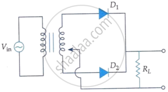
A full wave rectifier circuit diodes (D1) and (D2) is shown in the figure. If input supply voltage Vin = 220 sin (100 πt) volt, then at t = 15 ms.
What is the V-I characteristic curve of a diode?
Which formula gives the forward dynamic (AC) resistance?
Which expression applies Ohm's law to reverse-biased resistance?
