Advertisements
Advertisements
प्रश्न
In the circuit shown in figure, when the input voltage of the base resistance is 10 V, Vbe is zero and Vce is also zero. Find the values of Ib, Ic and β.

Advertisements
उत्तर
According to the problem, Vi = 10 V, Resistance, RB = 400 kΩ, VBE = 0, VCE = 0 and RC = 3 kΩ
`V_i - V_(BE) = R_BI_B`
`I_B = ("Voltage across" R_B)/R_B`
= `10/(400 xx 10^3)`
= `25 xx 10^-6` A
= 25 μA
Voltage across RC = 10 V
`V_(CC) - V_(CE) = I_CR_C`
`I_C = ("Voltage across" R_C)/R_C`
= `10/(3 xx 10^3)`
= `3.33 xx 10^-3` A
= 3.33 mA
β = `I_C/I_B`
= `(3.33 xx 10^-3)/(25 xx 10^-6)`
= `1.33 xx 10^2`
= 133
APPEARS IN
संबंधित प्रश्न
(i) Explain with the help of a diagram the formation of depletion region and barrier potential in a pn junction.
What happens when a forward bias is applied to a p-n junction?
What is the use of Zener diode?
Plot a graph showing variation of current versus voltage for the material GaAs ?
The graph shown in the figure represents a plot of current versus voltage for a given semiconductor. Identify the region, if any, over which the semiconductor has a negative resistance.

The plate current in a diode is 20 mA when the plate voltage is 50 V or 60 V. What will be the current if the plate voltage is 70 V?
Diffusion in a p-n junction is due to ______.
In a semiconductor diode, the barrier potential offers opposition to only
In Figure, Vo is the potential barrier across a p-n junction, when no battery is connected across the junction ______.

Consider an npn transistor with its base-emitter junction forward biased and collector base junction reverse biased. Which of the following statements are true?
- Electrons crossover from emitter to collector.
- Holes move from base to collector.
- Electrons move from emitter to base.
- Electrons from emitter move out of base without going to the collector.
Consider an npn transistor with its base-emitter junction forward biased and collector base junction reverse biased. Which of the following statements are true?
- Electrons crossover from emitter to collector.
- Holes move from base to collector.
- Electrons move from emitter to base.
- Electrons from emitter move out of base without going to the collector.
Describe the following term briefly:
Minority carrier injection in forward biasing.
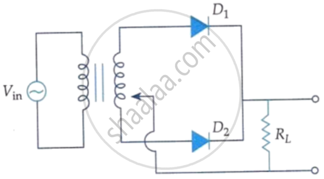
A full wave rectifier circuit diodes (D1) and (D2) is shown in the figure. If input supply voltage Vin = 220 sin (100 πt) volt, then at t = 15 ms.
Which charge carriers are present in large numbers in an n-type semiconductor?
What is the approximate cut-in voltage of a germanium diode?
What is the V-I characteristic curve of a diode?
What happens to reverse current at the breakdown voltage?
Which expression applies Ohm's law to reverse-biased resistance?
