Advertisements
Advertisements
Question
The dynamic plate resistance of a triode value is 10 kΩ. Find the change in the plate current if the plate voltage is changed from 200 V to 220 V.
Advertisements
Solution
Given:-
Plate resistance,
`r_p=10kOmega=10^4Omega`
Change in plate voltage,
`deltaV_p=220-200=20V`
Plate resistance at constant grid voltage is given as:-
\[r_P = \left(\frac{\delta V_P}{\delta I_P}\right)_{V_G = Constant} \]
\[ \Rightarrow \delta I_P = \frac{\delta V_P}{r_P}\]
\[\delta I_P = \frac{\delta V_p}{r_P}\]
\[\delta I_P = \frac{20}{{10}^4} = 0 . 002 A = 2\text{ mA}\]
APPEARS IN
RELATED QUESTIONS
What happens when a forward bias is applied to a p-n junction?
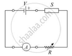
In the following diagram 'S' is a semiconductor. Would you increase or decrease the value of R to keep the reading of the ammeter A constant when S is heated? Give reason for your answer.
Draw a labelled diagram of a full wave rectifier. Show how output voltage varies with time if the input voltage is a sinusoidal voltage.
Why is a zener diode considered as a special purpose semiconductor diode?
A triode value operates at Vp = 225 V and Vg = −0.5 V.
The plate current remains unchanged if the plate voltage is increased to 250 V and the grid voltage is decreased to −2.5 V. Calculate the amplification factor.
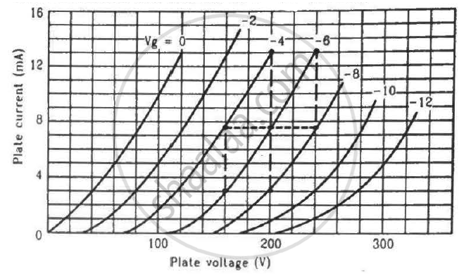
Find the values of rp, µ and gm of a triode operating at plate voltage 200 V and grid voltage −6. The plate characteristics are shown in the figure.
In semiconductor physics, what is meant by:
(i) rectifier
(ii) an amplifier
(iii) an oscillator
Answer the following question.
Why photodiodes are required to operate in reverse bias? Explain.
What are the applications of p - n Junction diode?
A – pn junction has a depletion layer of thickness .of the order of
The nature of binding for a crystal with alternate and evenly spaced positive and negatively ions is
In the circuit shown in figure, if the diode forward voltage drop is 0.3 V, the voltage difference between A and B is ______.

Can the potential barrier across a p-n junction be measured by simply connecting a voltmeter across the junction?
A Zener of power rating 1 W is to be used as a voltage regulator. If zener has a breakdown of 5 V and it has to regulate voltage which fluctuated between 3 V and 7 V, what should be the value of Rs for safe operation (Figure)?

Draw the circuit arrangement for studying V-I characteristics of a p-n junction diode in (i) forward biasing and (ii) reverse biasing. Draw the typical V-I characteristics of a silicon diode.
Describe the following term briefly:
Breakdown voltage in reverse biasing
When the p-side and n-side are joined, in which direction do holes diffuse?
What occurs near the junction when the p-side and n-side are joined?
Which voltage corresponds to a forward current of \[10\,\mathrm{mA}\]?
