Advertisements
Advertisements
Question
In the circuit shown in figure, if the diode forward voltage drop is 0.3 V, the voltage difference between A and B is ______.

Options
1.3 V
2.3 V
0
0.5 V
Advertisements
Solution
In the circuit shown in figure, if the diode forward voltage drop is 0.3 V, the voltage difference between A and B is 2.3 V.
Explanation:
Let us consider figure 2.3 V given above in the problem, suppose the potential difference between A and B is VAB.
Then, `V_(AB) - 0.3 = [(r_1 + r_2)10^3] xx (0.2 xx 10^-3)` .....[∵ VAB = ir]
= `[(5 + 5)10^3] xx (0.2 xx 10^-3)]`
= `10 xx 10^3 xx 0.2 xx 10^-3`
= 2
⇒ VAB = 2 + 0.3 = 2.3 V
APPEARS IN
RELATED QUESTIONS
Explain the working of P-N junction diode in forward and reverse biased mode.
What is the use of Zener diode?
The graph shown in the figure represents a plot of current versus voltage for a given semiconductor. Identify the region, if any, over which the semiconductor has a negative resistance.

Why is a zener diode considered as a special purpose semiconductor diode?
In a photo diode, the conductive increases when the material is exposed to light. It is found that the conductivity changes only if the wavelength is less than 620 nm. What is the band gap?
(Use Planck constant h = 4.14 × 10⁻¹⁵ eV-s, Boltzmann constant k = 8·62 × 10-5 eV/K.)
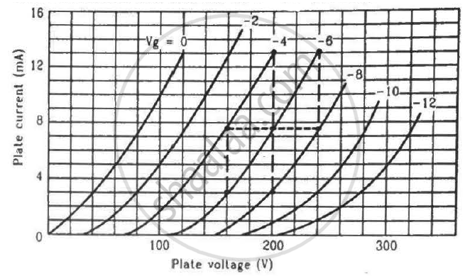
Find the values of rp, µ and gm of a triode operating at plate voltage 200 V and grid voltage −6. The plate characteristics are shown in the figure.
Answer the following question.
Why photodiodes are required to operate in reverse bias? Explain.
Diffusion in a p-n junction is due to ______.
With reference to Semiconductor Physics,
Name the diode that emits spontaneous radiation when forward biased.
The current through an ideal PN-junction shown in the following circuit diagram will be:

A – pn junction has a depletion layer of thickness .of the order of
In forward bias width of potential barrier in a p + n junction diode
Use a transistor as an amplition
On increasing the reverse biases voltage to a large value in a P – N junction diode-current
When an electric field is applied across a semiconductor ______.
- electrons move from lower energy level to higher energy level in the conduction band.
- electrons move from higher energy level to lower energy level in the conduction band.
- holes in the valence band move from higher energy level to lower energy level.
- holes in the valence band move from lower energy level to higher energy level.
Consider an npn transistor with its base-emitter junction forward biased and collector base junction reverse biased. Which of the following statements are true?
- Electrons crossover from emitter to collector.
- Holes move from base to collector.
- Electrons move from emitter to base.
- Electrons from emitter move out of base without going to the collector.
Draw V-I characteristics of a p-n Junction diode.
Describe the following term briefly:
Minority carrier injection in forward biasing.
What is meant by forward biasing of a semiconductor diode?
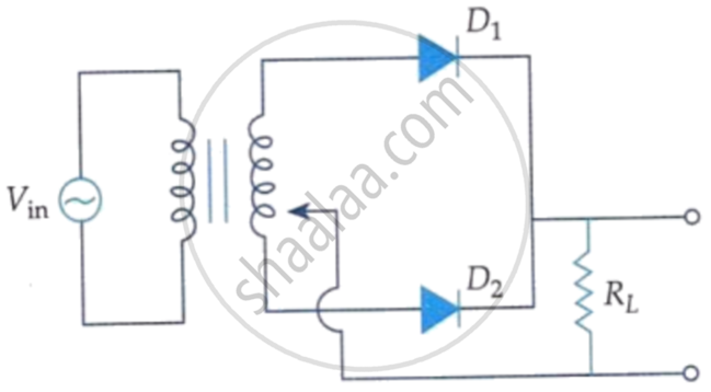
A full wave rectifier circuit diodes (D1) and (D2) is shown in the figure. If input supply voltage Vin = 220 sin (100 πt) volt, then at t = 15 ms.