Advertisements
Advertisements
प्रश्न
The plate current in a diode is 20 mA when the plate voltage is 50 V or 60 V. What will be the current if the plate voltage is 70 V?
Advertisements
उत्तर
For 50 V or 60 V, the plate current is 20 mA. That means 20 mA is the saturation current.
At the given temperature, the plate current is 20 mA for all other values of voltages.
Thus, the current at 70 V will be 20 mA.
APPEARS IN
संबंधित प्रश्न
Explain the working of P-N junction diode in forward and reverse biased mode.
The graph shown in the figure represents a plot of current versus voltage for a given semiconductor. Identify the region, if any, over which the semiconductor has a negative resistance.

The power delivered in the plate circular of a diode is 1.0 W when the plate voltage is 36 V. Find the power delivered if the plate voltage is increased to 49 V. Assume Langmuir-Child equation to hold.
The dynamic plate resistance of a triode value is 10 kΩ. Find the change in the plate current if the plate voltage is changed from 200 V to 220 V.
What are the applications of p - n Junction diode?
Depletion layer in p - n junction diode consists of
The nature of binding for a crystal with alternate and evenly spaced positive and negatively ions is
In forward bias width of potential barrier in a p + n junction diode
On increasing the reverse biases voltage to a large value in a P – N junction diode-current
Figure shows the transfer characteristics of a base biased CE transistor. Which of the following statements are true?

At Vi = 0.4 V, transistor is in active state.
At Vi = 1 V, it can be used as an amplifier.
At Vi = 0.5 V, it can be used as a switch turned off.
At Vi = 2.5 V, it can be used as a switch turned on.
A Zener of power rating 1 W is to be used as a voltage regulator. If zener has a breakdown of 5 V and it has to regulate voltage which fluctuated between 3 V and 7 V, what should be the value of Rs for safe operation (Figure)?

Differentiate between the threshold voltage and the breakdown voltage for a diode.
Write the property of a junction diode which makes it suitable for rectification of ac voltages.
Answer the following giving reasons:
A p-n junction diode is damaged by a strong current.
Describe the following term briefly:
Minority carrier injection in forward biasing.
With reference to a semiconductor diode, define the depletion region.
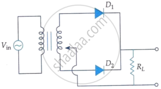
A full wave rectifier circuit diodes (D1) and (D2) is shown in the figure. If input supply voltage Vin = 220 sin (100 πt) volt, then at t = 15 ms.
Choose the correct circuit which can achieve the bridge balance.
