Advertisements
Advertisements
प्रश्न
A triode value operates at Vp = 225 V and Vg = −0.5 V.
The plate current remains unchanged if the plate voltage is increased to 250 V and the grid voltage is decreased to −2.5 V. Calculate the amplification factor.
Advertisements
उत्तर
Amplification factor for a triode valve,
\[\mu = \frac{\text{Change in Plate Voltage}}{\text{Change in Grid Voltage}}\]
At constant plate current,
\[\mu = \left(\frac{\delta V_P}{\delta V_G}\right)_{i_P = constant} \]
\[\mu = \frac{250 - 225}{2 . 5 - 0 . 5}\]
\[\mu = \frac{25}{2} = 12 . 5\]
This implies that the amplification factor of the triode is 12.5
APPEARS IN
संबंधित प्रश्न
Explain the working of P-N junction diode in forward and reverse biased mode.
What happens when a forward bias is applied to a p-n junction?
What causes the setting up of high electric field even for small reverse bias voltage across the diode?
In the following diagram, is the junction diode forward biased or reverse biased ?
With reference to semiconductor devices, define a p-type semiconductor and a Zener diode.
Plot a graph showing variation of current versus voltage for the material GaAs ?
In a photo diode, the conductive increases when the material is exposed to light. It is found that the conductivity changes only if the wavelength is less than 620 nm. What is the band gap?
(Use Planck constant h = 4.14 × 10⁻¹⁵ eV-s, Boltzmann constant k = 8·62 × 10-5 eV/K.)
The power delivered in the plate circular of a diode is 1.0 W when the plate voltage is 36 V. Find the power delivered if the plate voltage is increased to 49 V. Assume Langmuir-Child equation to hold.
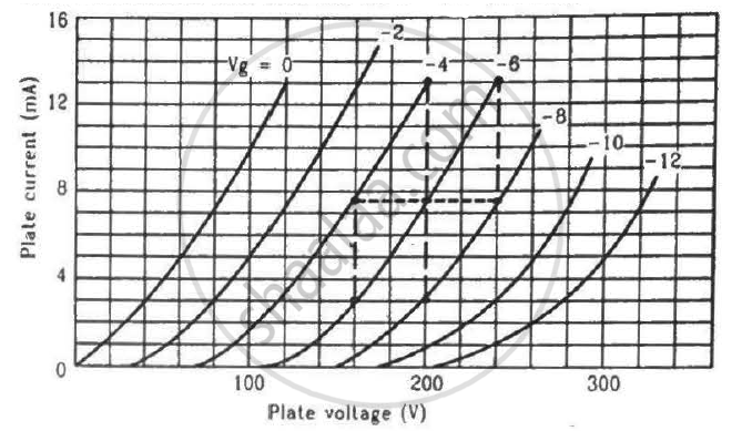
Find the values of rp, µ and gm of a triode operating at plate voltage 200 V and grid voltage −6. The plate characteristics are shown in the figure.
We use alloys for making standard resistors because they have ____________.
Of the diodes shown in the following diagrams, which one is reverse biased?
Depletion layer in p - n junction diode consists of
When we apply reverse biased to a junction diode, it
The nature of binding for a crystal with alternate and evenly spaced positive and negatively ions is
Avalanche breakdown is due to ______.
In the circuit shown in figure, if the diode forward voltage drop is 0.3 V, the voltage difference between A and B is ______.

Differentiate between the threshold voltage and the breakdown voltage for a diode.
Explain the formation of the barrier potential in a p-n junction.
Read the following paragraph and answer the questions that follow.
| A semiconductor diode is basically a pn junction with metallic contacts provided at the ends for the application of an external voltage. It is a two-terminal device. When an external voltage is applied across a semiconductor diode such that the p-side is connected to the positive terminal of the battery and the n-side to the negative terminal, it is said to be forward-biased. When an external voltage is applied across the diode such that the n-side is positive and the p-side is negative, it is said to be reverse-biased. An ideal diode is one whose resistance in forward biasing is zero and the resistance is infinite in reverse biasing. When the diode is forward biased, it is found that beyond forward voltage called knee voltage, the conductivity is very high. When the biasing voltage is more than the knee voltage the potential barrier is overcome and the current increases rapidly with an increase in forward voltage. When the diode is reverse biased, the reverse bias voltage produces a very small current of about a few microamperes which almost remains constant with bias. This small current is a reverse saturation current. |
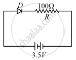
- In the given figure, a diode D is connected to an external resistance R = 100 Ω and an emf of 3.5 V. If the barrier potential developed across the diode is 0.5 V, the current in the circuit will be:
(a) 40 mA
(b) 20 mA
(c) 35 mA
(d) 30 mA - In which of the following figures, the pn diode is reverse biased?
(a)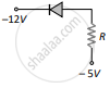
(b)
(c)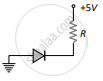
(d)
- Based on the V-I characteristics of the diode, we can classify the diode as:
(a) bilateral device
(b) ohmic device
(c) non-ohmic device
(d) passive element
OR
Two identical PN junctions can be connected in series by three different methods as shown in the figure. If the potential difference in the junctions is the same, then the correct connections will be:
(a) in the circuits (1) and (2)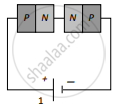

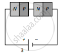
(b) in the circuits (2) and (3)
(c) in the circuits (1) and (3)
(d) only in the circuit (1) 
The V-I characteristic of a diode is shown in the figure. The ratio of the resistance of the diode at I = 15 mA to the resistance at V = -10 V is
(a) 100
(b) 106
(c) 10
(d) 10-6
Which practical effect is associated with forward bias?
