Advertisements
Advertisements
प्रश्न
Draw the current-voltage characteristics for the device show in figure between the terminals A and B.
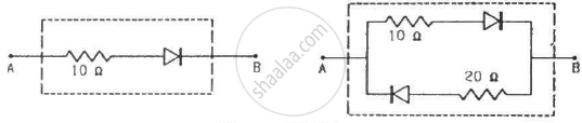
(Assume that the resistance of each diode is zero in forward bias and is infinity in reverse bias.)
Advertisements
उत्तर
(a) If a battery is connected between terminals A and B, with positive terminal connected to point A and negative terminal connected to point B, then the diode will get forward biassed by the applied voltage. So, the current voltage graph for this circuit will be the same as that of the characteristic curves of a forward-biassed diode.
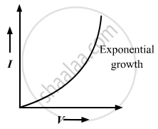
(b) If a battery is connected between terminals A and B, with positive terminal connected to point A and negative terminal connected to point B, then the upper diode will get forward biassed and the lower diode will get reverse biassed by the applied voltage. So, this lower branch can be replaced by an open circuit; hence, the current flow through this branch will be zero. The current flows only through the upper diode, so the circuit on simplification will become identical to the circuit in part (a). Hence, the current voltage graph for this circuit will be the same as that of the characteristic curves of a forward-biassed diode.
APPEARS IN
संबंधित प्रश्न
Explain briefly with the help of necessary diagrams, the reverse biasing of a p-n junction diode. Also draw characteristic curves.
Draw a circuit diagram to study the input and output characteristics of an n-p-n transistor in its common emitter configuration. Draw the typical input and output characteristics.
Two identical p-n junction may be connected in series with a battery in three ways. The potential difference across the two p-n junctions are equal in

A semiconducting device is connected in a series circuit with a battery and a resistance. A current is found to pass through the circuit. If the polarity of the battery is reversed, the current drops to almost zero. the device may be
(a) an intrinsic semiconductor
(b) a p-type semiconductor
(c) an n-type semiconductor
(d) a p-n junction
The potential barrier existing across an unbiased p-n junction is 0.2 volt. What minimum kinetic energy a hole should have to diffuse from the p-side to the n-side if (a) the junction is unbiased, (b) the junction is forward-biased at 0.1 volt and (c) the junction is reverse-biased at 0.1 volt?
The current−voltage characteristic of an ideal p-n junction diode is given by \[i = i_0 ( e^{eV/KT} - 1)\] where, the drift current i0 equals 10 µA. Take the temperature T to be 300 K. (a) Find the voltage V0 for which \[e^{eV/kT} = 100 .\]One can neglect the term 1 for voltages greater than this value. (b) Find an expression for the dynamic resistance of the diode as a function of V for V > V0. (c) Find the voltage for which the dynamic resistance is 0.2 Ω.
(Use Planck constant h = 4.14 × 10⁻¹⁵ eV-s, Boltzmann constant k = 8·62 × 10-5 eV/K.)
What are the readings of the ammeters A1 and A2 shown in figure. Neglect the resistance of the meters.
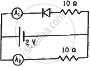
(Assume that the resistance of each diode is zero in forward bias and is infinity in reverse bias.)
A diode, a resistor and a 50 Hz AC source are connected in series. The number of current pulses per second through the resistor is __________ .
If in a p-n junction diode, a square input signal of 10 V is applied as shown Then the output signal across RL will be ______

p-n junction diode is formed
For an ideal diode, in forward and reverse biased condition the resistance is respectively ______.
In p-n junction diode ______.
What is drift?
Which charge carriers remain near the junction after the region loses mobile charge carriers?
Why does microscopic roughness prevent a proper crystal lattice from forming between separate p-type and n-type slabs?
How is a true p-n junction created instead of physically joining separate semiconductor pieces?
What is the use of diodes in power supplies and chargers?
In which circuits are diodes used for signal detection?
Which formula gives the static resistance of a diode?
