Advertisements
Advertisements
Which statement/statement is/are correct?
1. An ammeter is connected in series in a circuit and a voltmeter is connected in parallel.
2. An ammeter has a high resistance.
3. A voltmeter has a low resistance.
(a) 1, 2, 3
(b) 1, 2
(c) 2, 3
(d) 1
Concept: undefined >> undefined
Which unit could be used to measure current?
(a) Watt
(b) Coulomb
(c) Volt
(d) Ampere
Concept: undefined >> undefined
Advertisements
If the current through a floodlamp is 5 A, what charge passed in 10 seconds?
(a) 0.5 C
(b) 2 C
(c) 5 C
(d) 50 C
Concept: undefined >> undefined
If the amount of electric charge passing through a conductor in 10 minutes is 300 C, the current flowing is:
(a) 30 A
(b) 0.3 A
(c) 0.5 A
(d) 5 A
Concept: undefined >> undefined
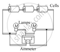
A student made an electric circuit shown here to measure the current through two lamps.
Are the lamps in series or parallel?
(a) Are the lamps in series or parallel?
(b) The student has made a mistake in this circuit. What is the mistake?
(c) Draw a circuit diagram to show the correct way to connect the circuit. Use the proper circuit symbols in your diagram.
Concept: undefined >> undefined
How many electrons are flowing per second past a point in a circuit in which there is a current of 5 amp?
Concept: undefined >> undefined
State the factors on which the strength of electric current flowing in a given conductor depends.
Concept: undefined >> undefined
An electric circuit consisting of a 0.5 m long nichrome wire XY, an ammeter, a voltmeter, four cells of 1.5 V each and a plug key was set up.
(i) Draw a diagram of this electric circuit to study the relation between the potential difference maintained between the points 'X' and 'Y' and the electric current flowing through XY.
Concept: undefined >> undefined
An electric circuit consisting of a 0.5 m long nichrome wire XY, an ammeter, a voltmeter, four cells of 1.5 V each and a plug key was set up.
Following graph was plotted between V and I values:
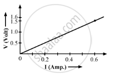
What would be the values of `V/I` rations when the potential difference is 0.8 V, 1.2 V and 1.6 V respectively?
What conclusion do you draw from these values?
What is the resistance of the wire?
Concept: undefined >> undefined
The p.d. across a 3 Ω resistor is 6 V. The current flowing in the resistor will be:
(a) `1/2A`
(b) 1 A
(c) 2 A
(d) 6 A
Concept: undefined >> undefined
A car headlight bulb working on a 12 V car battery draws a current of 0.5 A. The resistance of the light bulb is:
(a) 0.5 Ω
(b) 6 Ω
(c) 12 Ω
(d) 24 Ω
Concept: undefined >> undefined
A battery of 9 V is connected in series with resistors of 0.2 Ω, 0.3 Ω, 0.4 Ω, 0.5 Ω and 0.12 Ω. How much current would flow through the 12 Ω resistor?
Concept: undefined >> undefined
An electric bulb of resistance 20 Ω and a resistance wire of 4 Ω are connected in series with a 6 V battery.
Draw the circuit diagram, and calculate:
(a) total resistance of the circuit.
(b) current through the circuit.
(c) potential difference across the electric bulb.
(d) potential difference across the resistance wire.
Concept: undefined >> undefined
Three resistors are connected as shown in the diagram.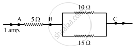
Through the resistor 5 ohm, a current of 1 ampere is flowing.
(i) What is the current through the other two resistors?
(ii) What is the p.d. across AB and across AC?
(iii) What is the total resistance
Concept: undefined >> undefined
The circuit diagram given below shows the combination of three resistors R1, R2 and R3:
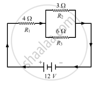
Find :
(i) total resistance of the circuit.
(ii) total current flowing in the circuit.
(iii) the potential difference across R1.
Concept: undefined >> undefined
In the circuit diagram given below five resistances of 10 Ω, 40 Ω, 30 Ω, 20 Ω, and 60 Ω are connected as shown to a 12 V battery.
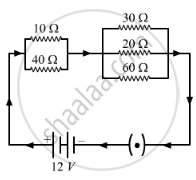
Calculate:
(a) total resistance in the circuit.
(b) total current flowing in the circuit.
Concept: undefined >> undefined
In the circuit diagram given below, three resistors R1, R2, and R3 of 5 Ω, 10 Ω and 30 Ω, respectively are connected as shown
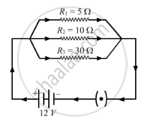
Calculate:
- current through each resistor.
- total current in the circuit.
- total resistance in the circuit.
Concept: undefined >> undefined
A p.d. of 6 V is applied to two resistors of 3 Ω and 6 Ω connected in parallel. Calculate:
(a) the combined resistance
(b) the current flowing in the main circuit
(c) the current flowing in the 3 Ω resistor.
Concept: undefined >> undefined
In the circuit shown below, the voltmeter reads 10 V.
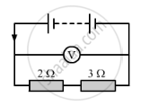
(a) What is the combined resistance?
(b) What current flows?
(c) What is the p.d. across 2 Ω resistor?
(d) What is the p.d. across 3 Ω resistor?
Concept: undefined >> undefined
A 5 V battery is connected to two 20 Ω resistors which are joined together in series.
(a) Draw a circuit diagram to represent this. Add an arrow to indicate the direction of conventional current flow in the circuit.
(b) What is the effective resistance of the two resistors?
(c) Calculate the current that flows from the battery?
(d) What is the p.d. across each resistor?
Concept: undefined >> undefined
