Advertisements
Advertisements
Question
In the circuit diagram given below, three resistors R1, R2, and R3 of 5 Ω, 10 Ω and 30 Ω, respectively are connected as shown
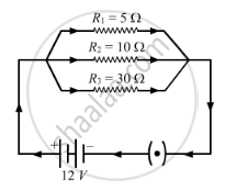
Calculate:
- current through each resistor.
- total current in the circuit.
- total resistance in the circuit.
Advertisements
Solution
a. Let I1, I2 and I3 be the current flowing through the resistors of 5 Ω, 10 Ω and 30 Ω, respectively.
According to Ohm's law, V = IR
Here, V = 12 V and R = 5 Ω
`I = V/R`
`I_1 = 12/5 = 2.4 A`
`I_2 = 12/10 = 1.2 A`
`I_3 = 12/30 = 0.4 A`
b. Total current through the circuit, I = I1 + I2 + I3
= 2.4 A + 1.2 A + 0.4 A
= 4 A
c. The resistors of 5 Ω, 10 Ω and 30 Ω are connected in parallel. Therefore, the net resistance will be:
`1/ R = 1/R_1 + 1/R_2 + 1/R_3`
`1/R = (1/5) + (1/10) + (1/30)`
`1/R = (6 + 3 +1)/30`
`I/R = 10/30`
R = 3 Ω
APPEARS IN
RELATED QUESTIONS
What is the Flow of Charge Called?
What is an Ammeter? How is It Connected in a Circuit? Draw a Diagram to Illustrate Your Answer.
An electric bulb of resistance 20 Ω and a resistance wire of 4 Ω are connected in series with a 6 V battery.
Draw the circuit diagram, and calculate:
(a) total resistance of the circuit.
(b) current through the circuit.
(c) potential difference across the electric bulb.
(d) potential difference across the resistance wire.
Which type of circuit, series or parallel, is preferred while connecting a large number of bulbs:
(a) for decorating a hotel building from outside?
Which type of circuit, series or parallel, is preferred while connecting a large number of bulbs:
(b) for lighting inside the rooms of the hotel?
Christmas tree lamps are usually wired in series. What happens if one lamps breaks?
Using the circuit given below, state which of the following statement is correct?
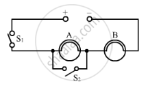
(a) When S1 and S2 are closed, lamps A and B are lit.22
(b) With S1 open and S2 closed, A is lit and B is not lit.
(c) With S2 open and S1 closed A and B are lit.
(d) With S1 closed and S2 open, lamp A remains lit even if lamp B gets fused.
Which effect of current is utilised in the working of an electric fuse?
An electric current flowing in a wire creates ______ around the wire.
A bulb of 40 W is used for 12.5 h each day for 30 days. Calculate the electrical energy consumed.
An electric iron is rated 750 W, 230 V. Calculate the electrical energy consumed by the press in 16 hours.
Kilowatt hour is the unit of
The SI unit for electric current is the coulomb.
What is the SI unit for the current?
