Advertisements
Advertisements
Question
What is the potential difference?
Advertisements
Solution
The potential difference is the difference in the electric potential of two different points.
APPEARS IN
RELATED QUESTIONS
Draw circuit symbols for
fixed resistance
Draw circuit symbols for
a battery of three cells
Draw circuit symbols for
an open switch
Explain with the help of a labelled circuit diagram how you will find the resistance of a combination of three resistors, or resistance R1, R2 and R3, joined in parallel. Also mention how you will connect the ammeter and the voltmeter in the circuit when measuring the current in the circuit and the potential difference across one of the three resistors of the combination.
Explain the construction and working of the following. Draw a neat diagram and label it.
Electric motor
Who will spend more electrical energy? 500 W TV Set in 30 mins, or 600 W heater in 20 mins?
In an electric circuit, electron flow a from of point of ______ potential to the point of ______ potential.
Draw a neat diagram showing a open electric circuit.
Name the instrument used to control current in an electric circuit.
In any electric circuit, when the switch is on and the current flows through it why do the wire, switches, bulb or devices become hot?
How much is the potential difference between live and neutral wires?
Right or wrong sentence.
Increasing the current passing through the wire decreases the magnetic field intensity.
What is the use of earthing wire?
______ is the device used to close or open an electric circuit.
In which among the following circuits does the bulb glow?
Higher Order Question
A student made a circuit by using an electric cell, a switch, a torch bulb (fitted in the bulb holder), and copper connecting wires. When he turned on the switch, the torch bulb did not glow at all. The student checked the circuit and found that all the wire connections were tight.
- What could be the possible reason for the torch bulb not glowing even when the circuit appears to be complete?
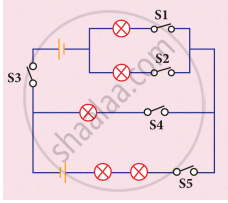
Study the electric circuit below. Which of the following switches should be closed so that only two bulbs will light up
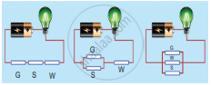
Study the three electric circuits below. Each of them has a glass rod (G), a steel rod (S), and a wooden rod (W).
In which of the electric circuits would the bulb not light up.
Which of the following a simple circuit must-have?
Fuse is
_____ has a thin metallic filament that melts and breaks the connection when the circuit is overheated.
In a simple circuit, why does the bulb glow when you close the switch?
When a circuit is open, _____ cannot pass through it.
The wiring in a house consists of ______ circuits.
Explain about domestic electric circuits. (circuit diagram not required)
The rate of flow of electric charges in a circuit is called ______.
A child has drawn the electric circuit to study Ohm’s law as shown in Figure. His teacher told that the circuit diagram needs correction. Study the circuit diagram and redraw it after making all corrections.

In an electric circuit, the current starts from ______.
Choose the statement which is not correct in the case of an electric fuse.

In the above circuit, if the current reading in the ammeter A is 2A, what would be the value of R1?
Paheli connected two bulbs to a cell as shown in the following figure.
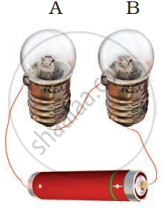
She found that filament of bulb B is broken. Will the bulb A glow in this circuit? Give reason.
Name the device which is used to measure the strength of the electric current in an electric circuit.
A complete circuit is left on for several minutes, causing the connecting copper wire to become hot. As the temperature of the wire increases, the electrical resistance of the wire
An electric motor rated 1100 W is connected to 220 V mains. Find:
- The current drawn from the mains,
- Electric energy consumed if the motor is used for 5 hours daily for 6 days.
- Total cost of energy consumed if the rate of one unit is 5.
Assertion: People struck by lightning receive a severe electrical shock.
Reason: Lightning carries very high voltage.
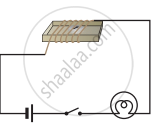
Set up the circuit shown in Figure again. Move the key to ‘ON’ position and watch carefully in which direction the compass needle gets deflected. Switch ‘OFF’ the current. Now keeping rest of the circuit intact, reverse the connections at the terminal of the cell. Again switch ‘on’ the current. Note the direction in which the needle gets deflected. Think of an explanation.