Advertisements
Advertisements
Questions
Explain the construction and working of the following. Draw a neat diagram and label it.
Electric motor
Explain the construction and working of electric motor in short.
Advertisements
Solution
- Construction: Electric motor consists of the following parts:
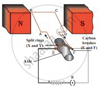
- Rectangular coil: A large number of turns of insulated copper wire wound on iron core in rectangular shape forms a coil ABCD as shown in following figure.
- Strong magnet: The coil is placed in between two pole pieces (N and S) of a strong horse shoe magnet which provides a strong magnetic field. The sides AB and CD are perpendicular to the direction of the magnetic field.
- Split ring: It consists of two halves of a metallic ring (X and Y). The ends of the coil are connected to these rings. The outer conducting surfaces of spilt rings X and Y are in contact with the two stationary carbon brushes. Spilt rings reverse the direction of current in the coil.
- Brushes: Two carbon brushes E and F are used to press the split rings.
- Axle: The two halves of the rings have a resistive coating in their inner surfaces and are tightly fitted on the axle. The main function of an axle is to rotate with the coil.
- Battery: The battery supplies the current to the coil.
- Working:
- When the circuit is completed, the current passes through the brush E from A to B in branch AB.
- As, the magnetic field acts from north pole to south pole, according to Fleming’s left-hand rule, the force experienced by arm AB is in the downward direction and arm CD is in the upward direction.
- Both these forces are equal in magnitude and opposite in direction and hence, the coil rotates in an anticlockwise direction.
- After half rotation, the split rings X and Y come in contact with brushes E and F respectively.
- Again the current starts passing through the coil in opposite direction.
- The force acting on branch BA is upward and DC is downward, this force again moves the coil in an anticlockwise direction.
- This shows that the current in the loop ABCD is reversed after every half rotation, and the loop continues to rotate in the same direction.
- Thus, the coil rotates with the help of electrical energy.
APPEARS IN
RELATED QUESTIONS
What do the following symbols mean in circuit diagrams?
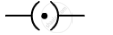
Draw circuit symbols for variable resistance
Draw circuit symbols for
a cell
Draw the labelled diagram of an electric circuit comprising of a cell, a resistance, an ammeter, a voltmeter and a closed switch (or closed plug key). Which of the two has a large resistance : an ammeter or a voltmeter?
Draw a circuit diagram to show how 3 bulbs can be lit from a battery so that 2 bulbs are controlled by the same switch the third bulb has its own switch.
How does the short circuit form?
The accompanying figure shows some electrical appliances connected in a circuit in a house. Answer the following questions.

- By which method are the appliances connected?
- What must be the potential difference across individual appliances?
- Will the current passing through each appliance be the same? Justify your answer.
- Why are the domestic appliances connected in this way?
- If the T.V. stops working, will the other appliances also stop working? Explain your answer.
In an electric circuit, electron flow a from of point of ______ potential to the point of ______ potential.
A battery is to be formed by joining 3 dry cells with connecting wires. Show how will you connect the wires by drawing a diagram.
In an electric circuit, a battery and a bulb have been connected and the battery consists of two cells of equal potential difference. If the bulb is not glowing, then which tests will you perform in order to find out the reason for the bulb not glowing?
Distinguish between a closed circuit and an open circuit, with the use of suitable labelled diagrams.
Answer the following question.
With the help of a suitable circuit diagram prove that the reciprocal of the equivalent resistance of a group of resistances joined in parallel is equal to the sum of the reciprocals of the individual resistances.
Draw a neat diagram showing a closed electric circuit.
Explain the following:
Open circuit
Right or wrong sentence.
Increasing the current passing through the wire decreases the magnetic field intensity.
Nowadays MCBs are used in homes, for stop the current in the circuit which suddenly increases.
______ is the device used to close or open an electric circuit.
Draw the circuit diagram for the series connection.
Higher Order Question
A student made a circuit by using an electric cell, a switch, a torch bulb (fitted in the bulb holder), and copper connecting wires. When he turned on the switch, the torch bulb did not glow at all. The student checked the circuit and found that all the wire connections were tight.
- What could be the possible reason for the torch bulb not glowing even when the circuit appears to be complete?
Three bulbs are connected end to end from the battery. This connection is called _______.
A device that is used to break an electric circuit is called ______.
Assertion: In an open circuit, the current passes from one terminal of the electric cell to another.
Reason: Generally, the metal disc of a cell acts as a positive terminal.
In an electrical circuit three incandescent bulbs A, B and C of rating 40 W, 60 W and 100 W respectively are connected in parallel to an electric source. Which of the following is likely to happen regarding their brightness?
Draw a circuit diagram of an electric circuit containing a cell, a key, an ammeter, a resistor of 2 Ω in series with a combination of two resistors (4 Ω each) in parallel and a voltmeter across the parallel combination. Will the potential difference across the 2 Ω resistor be the same as that across the parallel combination of 4 Ω resistors? Give reason.
In an electric circuit, the current starts from ______.
In the following arrangement shown in the following figure, the bulb will not glow if the ends A and B are connected with
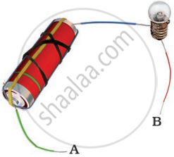
Boojho has a cell and a single piece of connecting wire. Without cutting the wire in two, will he be able to make the bulb glow? Explain with the help of a circuit diagram.
Write a short note on the different electrical circuits.
Overloading of electric circuits can lead to short-circuiting.
Name the device which is used to measure the strength of the electric current in an electric circuit.
Set up the circuit shown in Figure again. Move the key to ‘ON’ position and watch carefully in which direction the compass needle gets deflected. Switch ‘OFF’ the current. Now keeping rest of the circuit intact, reverse the connections at the terminal of the cell. Again switch ‘on’ the current. Note the direction in which the needle gets deflected. Think of an explanation.