Advertisements
Advertisements
Question
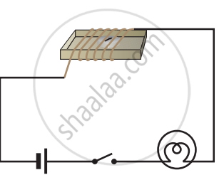
Set up the circuit shown in Figure again. Move the key to ‘ON’ position and watch carefully in which direction the compass needle gets deflected. Switch ‘OFF’ the current. Now keeping rest of the circuit intact, reverse the connections at the terminal of the cell. Again switch ‘on’ the current. Note the direction in which the needle gets deflected. Think of an explanation.
Advertisements
Solution

- Set up the Circuit:
- Connect the components as shown in the figure: battery, switch, wire wound around cardboard, and a compass.
- Turn the Switch 'ON':
- Close the switch to 'ON'.
- Observe and note the direction of the compass needle deflection.
- Turn the Switch 'OFF':
- Open the switch to 'OFF'.
- Reverse Battery Connections:
- Swap the positive and negative terminals of the battery.
- Turn the Switch 'ON' Again:
- Close the switch to 'ON'.
- Observe and note the direction of the compass needle deflection again.
- Explanation:
- The compass needle deflects due to the magnetic field created by the current.
- Reversing the battery connections reverses the current direction, thus reversing the magnetic field and the needle's deflection direction.
APPEARS IN
RELATED QUESTIONS
The following figure shows the symbols for components used in the accompanying electrical circuit. Place them at proper places and complete the circuit.
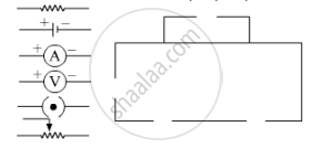
Which law can you prove with the help of above circuit?
Nowadays MCBs are used in homes, for stop the current in the circuit which suddenly increases.
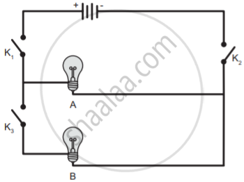
In the given circuit diagram, which of the given switch(s) should be closed. So that only bulb A glows.
Draw the circuit diagram for the series connection.
_____ has a thin metallic filament that melts and breaks the connection when the circuit is overheated.
Assertion: People struck by lightning receive a severe electrical shock.
Reason: Lightning carries very high voltage.
In a circuit, if the key is in open (off) condition, then electricity will not flow.
In an electric circuit a fuse is a ______ ______ to prevent possible fire.
How is Joule's law effect useful in electric circuits where fuse is used as a safety device?
