Advertisements
Advertisements
Question
Two cells of voltage 10V and 2V and internal resistances 10Ω and 5Ω respectively, are connected in parallel with the positive end of 10V battery connected to negative pole of 2V battery (Figure). Find the effective voltage and effective resistance of the combination.

Advertisements
Solution
In this problem first, we are applying Kirchhoff's junction rule at c, I1 = I + I2
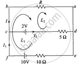
Applying Kirchhoff's voltage law in loop (e – f – b – a – e) loop L1 outer loop, then we get
10 – IR – 10l1 = 0
10 = IR + 10l1 ......(i)
Applying Kirchhoff's voltage law in loop (c – b – a – d – c) loop L2, we get
– 2 – IR + 5I2 = 0
2 = 5I2 – RI
As we know, I1 = I + I2 then
I2 = I1 – I
So the above equation can be written as
2 = 5(I1 – I) – RI
or 4 = 10I1 – 10I – 2RI ......(ii)
Subtracting equations (ii) from (i), we get
⇒ 6 = 3RI + 10I
2 = `I(R + 10/3)`
Also, the external resistance is R. The Ohm's law states that V = I(R + Reff)
On comparing, we have V = 2V and effective internal resistance `(R_("eff")) = (10/3)Ω`
Since, the equivalent internal resistance (Reff) of two cells is `(10/3)Ω`, being the parallel combination of 5Ω and 10Ω. The equivalent circuit is given below:

APPEARS IN
RELATED QUESTIONS
State the two Kirchhoff’s rules used in electric networks. How are there rules justified?
Use Kirchhoff's rules to obtain conditions for the balance condition in a Wheatstone bridge.
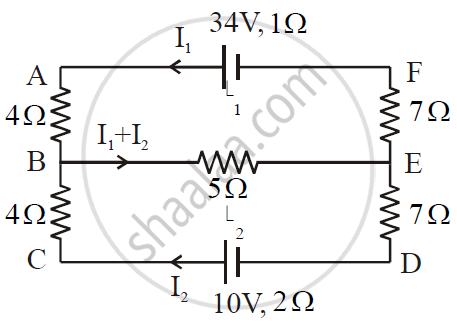
ε1 and ε2 are two batteries having emf of 34V and 10V respectively and internal resistance of 1Ω and 2Ω respectively. They are connected as shown in the figure below. Using Kirchhoff’s Laws of electrical networks, calculate the currents I1 and I2.
State Kirchhoff's rules and explain on what basis they are justified.
Given the resistances of 1 Ω, 2 Ω, 3 Ω, how will be combine them to get an equivalent resistance of (11/3) Ω?
Given the resistances of 1 Ω, 2 Ω, 3 Ω, how will be combine them to get an equivalent resistance of (11/5) Ω?
Given the resistances of 1 Ω, 2 Ω, 3 Ω, how will be combine them to get an equivalent resistance of 6 Ω?
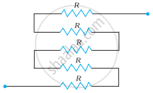
Determine the equivalent resistance of networks shown in Fig.
Using Kirchhoff’s rules determine the value of unknown resistance R in the circuit so that no current flows through 4 Ω resistance. Also find the potential difference between A and D.
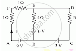
Calculate the value of the resistance R in the circuit shown in the figure so that the current in the circuit is 0.2 A. What would b the potential difference between points A and B?

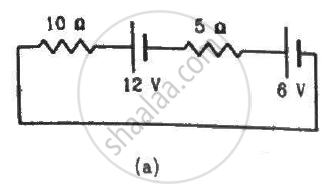
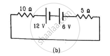
Consider the circuit shown in the figure. Find (a) the current in the circuit (b) the potential drop across the 5 Ω resistor (c) the potential drop across the 10 Ω resistor (d) Answer the parts (a), (b) and (c) with reference to the figure.
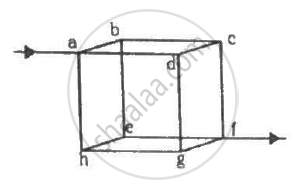
Twelve wires, each of equal resistance r, are joined to form a cube, as shown in the figure. Find the equivalent resistance between the diagonally-opposite points a and f.
State Kirchhoff ’s voltage rule.
State and explain Kirchhoff’s rules.
How the emf of two cells are compared using potentiometer?
Assertion: Kirchhoff’s junction rule follows from conservation of charge.
Reason: Kirchhoff’s loop rule follows from conservation of momentum.
While measuring the length of the rod by vernier callipers, the reading on the main scale is 6.4 cm and the eight divisions on vernier is in line with marking on the main scale division. If the least count of callipers is 0.01 and zero error - 0.04 cm, the length of the rod is ______.
The e.m.f of The battery in a thermocouple is doubled. The rate of heat generated at one of the junction will.
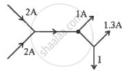
The figure below shows current in a part of electric circuit. The current I is ______.
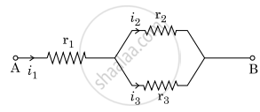
Three resistors having resistances r1, r2 and r3 are connected as shown in the given circuit. The ratio `"i"_3/"i"_1` of currents in terms of resistances used in the circuit is :
Kirchhoff’s junction rule is a reflection of ______.
- conservation of current density vector.
- conservation of charge.
- the fact that the momentum with which a charged particle approaches a junction is unchanged (as a vector) as the charged particle leaves the junction.
- the fact that there is no accumulation of charges at a junction.
The circuit in figure shows two cells connected in opposition to each other. Cell E1 is of emf 6V and internal resistance 2Ω; the cell E2 is of emf 4V and internal resistance 8Ω. Find the potential difference between the points A and B.
The value of current in the 6Ω resistance is ______.

In the circuit shown in Figure below, E1 and E2 are batteries having emfs of 25V and 26V. They have an internal resistance of 1 Ω and 5 Ω respectively. Applying Kirchhoff’s laws of electrical networks, calculate the currents I1 and I2.

The figure below shows two batteries, E1 and E2, having emfs of 18V and 10V and internal resistances of 1 Ω and 2 Ω, respectively. W1, W2 and W3 are uniform metallic wires AC, FD and BE having resistances of 8 Ω, 6 Ω and 10 Ω respectively. B and E are midpoints of the wires W1 and W2. Using Kirchhoff's laws of electrical circuits, calculate the current flowing in the wire W3:

Which two basic physical principles form the basis of Kirchhoff's laws?
What is a junction or node?
What is a branch?
Which term is defined as the rate of flow of charge through a conductor?
If currents \[I_1\] and \[I_2\] enter a junction and currents \[I_3\] and \[I_4\] leave it, which equation follows from Kirchhoff's First Law?
While moving in the direction of current through a resistor, how is the potential change treated?
At junction P, currents \[0.2\,\mathrm{A}\], \[0.6\,\mathrm{A}\], and \[0.7\,\mathrm{A}\] point towards P, while \[0.4\,\mathrm{A}\], \[0.5\,\mathrm{A}\], and \[I\] point away. What is the unknown current?
