Advertisements
Advertisements
प्रश्न
Two cells of voltage 10V and 2V and internal resistances 10Ω and 5Ω respectively, are connected in parallel with the positive end of 10V battery connected to negative pole of 2V battery (Figure). Find the effective voltage and effective resistance of the combination.

Advertisements
उत्तर
In this problem first, we are applying Kirchhoff's junction rule at c, I1 = I + I2
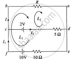
Applying Kirchhoff's voltage law in loop (e – f – b – a – e) loop L1 outer loop, then we get
10 – IR – 10l1 = 0
10 = IR + 10l1 ......(i)
Applying Kirchhoff's voltage law in loop (c – b – a – d – c) loop L2, we get
– 2 – IR + 5I2 = 0
2 = 5I2 – RI
As we know, I1 = I + I2 then
I2 = I1 – I
So the above equation can be written as
2 = 5(I1 – I) – RI
or 4 = 10I1 – 10I – 2RI ......(ii)
Subtracting equations (ii) from (i), we get
⇒ 6 = 3RI + 10I
2 = `I(R + 10/3)`
Also, the external resistance is R. The Ohm's law states that V = I(R + Reff)
On comparing, we have V = 2V and effective internal resistance `(R_("eff")) = (10/3)Ω`
Since, the equivalent internal resistance (Reff) of two cells is `(10/3)Ω`, being the parallel combination of 5Ω and 10Ω. The equivalent circuit is given below:

APPEARS IN
संबंधित प्रश्न
Use Kirchhoff's rules to obtain conditions for the balance condition in a Wheatstone bridge.
Given n resistors each of resistance R, how will you combine them to get the (i) maximum (ii) minimum effective resistance? What is the ratio of the maximum to minimum resistance?
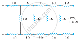
Determine the current drawn from a 12 V supply with internal resistance 0.5 Ω by the infinite network shown in the figure. Each resistor has 1 Ω resistance.
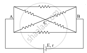
The current is drawn from a cell of emf E and internal resistance r connected to the network of resistors each of resistance r as shown in the figure. Obtain the expression for
- the current draw from the cell and
- the power consumed in the network.
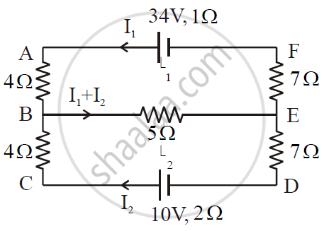
ε1 and ε2 are two batteries having emf of 34V and 10V respectively and internal resistance of 1Ω and 2Ω respectively. They are connected as shown in the figure below. Using Kirchhoff’s Laws of electrical networks, calculate the currents I1 and I2.
Given the resistances of 1 Ω, 2 Ω, 3 Ω, how will be combine them to get an equivalent resistance of (11/5) Ω?
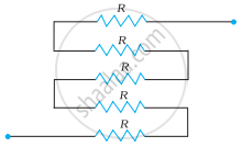
Determine the equivalent resistance of networks shown in Fig.
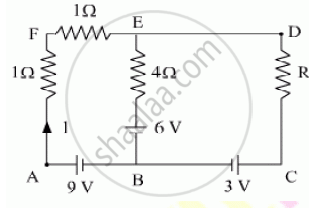
Using Kirchhoff’s rules determine the value of unknown resistance R in the circuit so that no current flows through 4 Ω resistance. Also find the potential difference between A and D.
Calculate the value of the resistance R in the circuit shown in the figure so that the current in the circuit is 0.2 A. What would b the potential difference between points A and B?

In the given circuit, assuming point A to be at zero potential, use Kirchhoff’s rules to determine the potential at point B.

A capacitor of capacitance 8.0 μF is connected to a battery of emf 6.0 V through a resistance of 24 Ω. Find the current in the circuit (a) just after the connections are made and (b) one time constant after the connections are made.
On which conservation principle is Kirchoff's Second Law of electrical networks based?
Solve the following question.
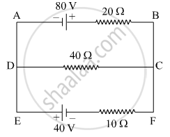
Using Kirchhoff’s rules, calculate the current through the 40 Ω and 20 Ω resistors in the following circuit.
Twelve wires each having a resistance of 3 Ω are connected to form a cubical network. A battery of 10 V and negligible internal resistance is connected across the diagonally opposite corners of this network. Determine its equivalent resistance and the current along each edge of the cube.
State Kirchhoff’s current rule.
State Kirchhoff ’s voltage rule.
State the principle of potentiometer.
Obtain the condition for bridge balance in Wheatstone’s bridge.
How the emf of two cells are compared using potentiometer?
A copper wire of 10-6 m2 area of cross-section, carries a current of 2 A. If the number of electrons per cubic meter is 8 × 1028, calculate the current density and average drift velocity.
The instrument for the accurate measurement of the e.m.f of a cell is ______.
The Kirchhoff's second law (ΣiR = ΣE), where the symbols have their usual meanings, is based on ______.
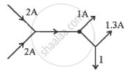
The figure below shows current in a part of electric circuit. The current I is ______.
Kirchhoff’s junction rule is a reflection of ______.
- conservation of current density vector.
- conservation of charge.
- the fact that the momentum with which a charged particle approaches a junction is unchanged (as a vector) as the charged particle leaves the junction.
- the fact that there is no accumulation of charges at a junction.
Power P is to be delivered to a device via transmission cables having resistance RC. If V is the voltage across R and I the current through it, find the power wasted and how can it be reduced.
A 6-volt battery is connected to the terminals of a three-metre-long wire of uniform thickness and resistance of 100 ohms. The difference of potential between two points on the wire separated by a distance of 50 cm will be ______.
In the circuit shown in Figure below, E1 and E2 are batteries having emfs of 25V and 26V. They have an internal resistance of 1 Ω and 5 Ω respectively. Applying Kirchhoff’s laws of electrical networks, calculate the currents I1 and I2.

Who gave Kirchhoff's laws?
At any junction, what does Kirchhoff's Current Law state?
What is Kirchhoff's Voltage Law also called?
What is a branch?
Which term is defined as the rate of flow of charge through a conductor?
What is emf?
Which algebraic form is equivalent to \[I_1+I_2=I_3+I_4\]?
